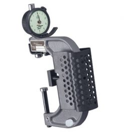
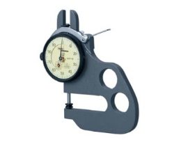
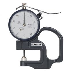
St. Mary Rotary “V” Block Gage
The precision St. Mary Rotary “V” Block Gage makes measuring concentricity characteristics on cold headed parts faster. easier, and more precise than other similar devices.
Geometric tolerancing measurement requirements are becoming more common on fasteners and cold formed specials.
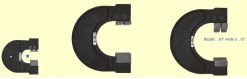
size diameters between the rolls: Unit will hold as small as .062″, and as large as 1.25″ diameters. Larger ones available
This item has been made temporarily obsolete and replaced by a unit with range of .06-1.1.” new unit called Spin Fixture TIR/FIM Gage. attached is the instruction manual for review
Read More
St. Mary Rotary "V" Block Gage Features:
- It is vital for fastener producers to have the capability to make these geometric, relational measurements accurately and repeatably
- The St. Mary gage design derives its accuracy and repeatability from its patented intermeshing three part contacting roll design.
- Other features contributing to its precision are an adjustable length stop, and adjustable spring loaded hold-down arm, sealed bearings, and lapped contact rolls
- On the smallest gage model, concentricity measurements as precise as .00005 inches can be made