

Your satisfaction enhances our reputation; we work diligently to maintain it.
It is important to note that color alone is not an indication of the physical qualities of the stone. In general, granite’s color is directly related to the presence or absence of minerals, which may have no bearing on the qualities that make good surface plate material. There are pink, gray, and black granites that are excellent for surface plates, as well as pink, gray, and black granites that are totally unsuitable for precision applications. The critical characteristics of granite, as they pertain to its use as a surface plate material, have nothing to do with color, and are as follows:
- Stiffness (deflection under load – indicated by Modulus of Elasticity)
- Hardness
- Density
- Wear resistance
- Stability
- Porosity
Most manufacturers use ASME B89.3.7-2013 or Federal Specification GGG-P-463c (Granite Surface Plates) as a basis for their specifications. You can access the ASME spec at asme.org or the GGG-P-463c here.
Flatness can be considered as all points on the surface being contained within two parallel planes, the base plane and the roof plane. The measurement of distance between the planes is the overall flatness of the surface. This flatness measurement commonly carries a tolerance and may include a grade designation.
The flatness tolerances for three standard grades are defined in the federal specification as determined by the following formula:
- Laboratory Grade AA = (40 + diagonal squared/25) x .000001″ (unilateral)
- Inspection Grade A = Laboratory Grade AA x 2
- Tool Room Grade B = Laboratory Grade AA x 4.
For standard sized surface plates, we guarantee flatness tolerances that exceed the requirements of this specification. In addition to flatness, ASME B89.3.7-2013 & Federal Specification GGG-P-463c address topics including: repeat measurement accuracy, material properties of surface plate granites, surface finish, support point location, stiffness, acceptable methods of inspection, installation of threaded inserts, etc.
Tru-Stone granite surface plates and granite inspection plates meet or exceed all of the requirements set forth in this specification. At present, there is no defining specification for granite angle plates, parallels, or master squares. Our standard tolerances for these items are the tightest in the precision granite industry.
First, it is important to keep the plate clean. Airborne abrasive dust is usually the greatest source of wear and tear on a plate, as it tends to embed in work pieces and the contact surfaces of gages. Second, cover your plate to protect it from dust and damage. Wear life can be extended by covering the plate when not in use, by rotating the plate periodically so that a single area does not receive excessive use, and by replacing steel contact pads on gauging with carbide pads. Also, avoid setting food or soft drinks on the plate. Note that many soft drinks contain either carbonic or phosphoric acid, which can dissolve the softer minerals and leave small pits in the surface.
This depends on how the plate is being used. If possible, we recommend cleaning the plate at the beginning of the day (or work shift) and again at the end. If the plate becomes soiled, particularly with oily or sticky fluids, it should probably be cleaned immediately.
Clean the plate regularly with Starrett liquid or Starrett Waterless surface plate cleaner. The choice of cleaning solutions is important. If a volatile solvent is used (acetone, lacquer thinner, alcohol, etc.) the evaporation will chill the surface, and distort it. In this case, it is necessary to allow the plate to normalize before using it or measurement errors will occur.
The amount of time required for the plate to normalize will vary with the size of the plate, and the amount of chilling. An hour should be sufficient for smaller plates. Two hours may be needed for larger plates. If a water-based cleaner is used, there will also be some evaporative chilling.
The plate will also retain the water, and this could cause rusting of metal parts in contact with the surface. Some cleaners will also leave a sticky residue after they dry, which will attract airborne dust, and actually increase wear, rather than decreasing it.
This depends on the plate usage and environment. We recommend that a new plate or precision granite accessory receive a full recalibration within one year of purchase. If the plate will see heavy use, it may be advisable to shorten this interval to six months. Monthly inspection for repeat measurement errors using a Repeat-o-Meter, or similar device will show any developing wear spots and only takes a few minutes to perform. After the results of the first recalibration are determined, the calibration interval may be extended or shortened as allowed or required by your internal quality system.
There are several possible causes for variations between calibrations:
- The surface was washed with a hot or cold solution prior to calibration, and was not allowed sufficient time to normalize
- The plate is improperly supported (See Q.16)
- Temperature change
- Drafts
- Direct sunlight or other radiant heat on the surface of the plate. Be sure that overhead lighting is not heating the surface
- Variations in the vertical temperature gradient between winter and summer (If at all possible, know the vertical gradient temperature at the time the calibration is performed.)
- Plate not allowed sufficient time to normalize after shipment
- Improper use of inspection equipment or use of non-calibrated equipment
- Surface change resulting from wear
A repeat measurement is a measurement of local flatness areas. The Repeat Measurement specification states that a measurement taken anywhere on the surface of a plate will repeat within the stated tolerance. Controlling local area flatness tighter than overall flatness guarantees a gradual change in surface flatness profile thereby minimizing local errors.
Most manufacturers, including imported brands, adhere to the Federal Specification of overall flatness tolerances but many overlook the repeat measurements. Many of the low value or budget plates available in the market today will not guarantee repeat measurements. A manufacturer who does not guarantee repeat measurements is NOT producing plates that meet the requirements of ASME B89.3.7-2013 or Federal Specification GGG-P-463c.
Both are critical to ensure a precision surface for accurate measurements. Flatness specification alone is not sufficient to guarantee measurement accuracy. Take as an example, a 36 X 48 Inspection Grade A surface plate, which meets ONLY the flatness specification of .000300″. If the piece being checked bridges several peaks, and the gage being used is in a low spot, the measurement error could be the full tolerance in one area, 000300″! Actually, it can be much higher if the gage is resting on the slope of an incline.
Errors of .000600″-.000800″ are possible, depending upon the severity of the slope, and the arm length of the gage being used. If this plate had a Repeat Measurement specification of .000050″F.I.R. then the measurement error would be less than .000050″ regardless of where the measurement is taken on the plate. Another problem, which usually arises when an untrained technician attempts to resurface a plate on-site, is the use of Repeat Measurements alone to certify a plate.
The instruments that are used to verify repeatability are NOT designed to check overall flatness. When set to zero on a perfectly curved surface, they will continue to read zero, whether that surface is perfectly flat or perfectly concave or convex 1/2″! They simply verify the uniformity of the surface, not the flatness. Only a plate that meets both the flatness specification AND the repeat measurement specification truly meets the requirements of ASME B89.3.7-2013 or Federal Specification GGG-P-463c.
Yes, but they can only be guaranteed for a specific vertical temperature gradient. The effects of thermal expansion on the plate could easily cause a change in accuracy greater than the tolerance if there is a change in the gradient. In some cases, if the tolerance is tight enough, the heat absorbed from overhead lighting can cause enough of a gradient change over several hours.
Granite has a coefficient of thermal expansion of approximately .0000035 inches per inch per 1°F. As an example: A 36″ x 48″ x 8″ surface plate has an accuracy of .000075″ (1/2 of Grade AA) at a gradient of 0°F, the top and bottom are the same temperature. If the top of the plate warms up to the point where it is 1°F warmer than the bottom, the accuracy would change to .000275″ convex ! Therefore, ordering a plate with a tolerance tighter than Laboratory Grade AA should only be considered if there is adequate climate control.
The answer is ‘yes’ for almost every application. The advantages of granite include: No rust or corrosion, almost immune to warping, no compensating hump when nicked, longer wear life, smoother action, greater precision, virtually non-magnetic, low co-efficient of thermal expansion, and low maintenance cost.
A surface plate should be supported at 3 points, ideally located 20% of the length in from the ends of the plate. Two supports should be located 20% of the width in from the long sides, and the remaining support should be centered. Only 3 points can rest solidly on anything but a precision surface.
The plate should be supported at these points during production, and it should be supported only at these three points while in use. Attempting to support the plate at more than three points will cause the plate to receive its support from various combinations of three points, which will not be the same 3 points on which it was supported during production. This will introduce errors as the plate deflects to conform to the new support arrangement.All Tru-Stone steel stands have support beams designed to line up with the proper support points.
If the plate is properly supported, precise leveling is only necessary if your application calls for it. Leveling is not necessary to maintain the accuracy of a properly supported plate.
Yes, if they are not too badly worn. Our factory setting and equipment allow the optimum conditions for proper plate calibration and rework if necessary. Generally, if a plate is within .001″ of the required tolerance, it can be resurfaced on-site. If a plate is worn to the point where it is more than .001″ out of tolerance, or if it is badly pitted or nicked, then it will need to be sent to the factory for grinding prior to relapping.
Great care should be exercised in selecting an on-site calibration and resurfacing technician. We urge you to use caution in selecting your calibration service. Ask for accreditation and verify the equipment that the technician will use has a NIST traceable calibration. It takes many years to learn how to properly lap precision granite.
Tru-Stone provides quick turn-around on calibrations performed in our factory. Send your plates in for calibration if possible. Your quality and reputation depend on the accuracy of your measurement instruments including surface plates!
Yes, but only at our factory. At our plant, we can restore almost any plate to ‘like-new’ condition, usually for less than half the cost of replacing it. Damaged edges can be cosmetically patched, deep grooves, nicks, and pits can be ground out, and the attached supports can be replaced. In addition, we can modify your plate to increase its versatility by adding solid or threaded steel inserts and cutting slots or clamping lips, per your specifications.
Our black surface plates have a significantly higher density and are up to three times as stiff. Therefore, a plate made of the Tru-Stone black does not need to be as thick as a granite plate of the same size to have equal or greater resistance to deflection. Reduced thickness means less weight and lower shipping costs.
Beware of others who use lower quality black granite in the same thickness. As stated above, properties of granite, like wood or metal, vary by material and color, and is not an accurate predictor of stiffness, hardness, or wear resistance. In fact, many types of black granite and diabase are very soft and not suitable for surface plate applications.
No. The specialized equipment and training necessary to rework these items requires that they be returned to the factory for calibration and rework.
No. Our equipment and calibration methods are designed for granite and do not work well on metal surfaces. Also, our lapping equipment will not work with metals, which generally requires hand-scraping to achieve the desired tolerances. Since hand-scraping is rapidly becoming a “lost art,” it is often more economical to replace a worn steel or cast iron plate with a new granite plate than it is to have the old plate re-scraped. There are many advantages of granite to the cast iron, as outlined earlier in this FAQ section.
Yes. Ceramic and granite have similar characteristics, and the methods used to calibrate and lap granite can be used with ceramic items as well. Ceramics are more difficult to lap than granite resulting in a higher cost.
Yes, provided that the inserts are recessed below the surface. If steel inserts are flush with, or above the surface plane, they must be spot-faced down before the plate can be lapped. If required, we can provide that service.
Yes. Steel inserts with the desired thread (English or metric) can be epoxy bonded into the plate at the desired locations. Tru-stone uses CNC machines to provide the tightest insert locations within +/- 0.005”. For less critical inserts, our locational tolerance for threaded inserts is ±.060″. Other options include steel T-Bars and dovetail slots machined directly into the granite.
Inserts that are properly bonded using high strength epoxy and good workmanship will withstand a great deal of torsional and shear force. In a recent test, using 3/8″-16 threaded inserts, an independent testing laboratory measured the force required to pull an epoxy-bonded insert from a surface plate. Ten plates were tested. Out of these ten, in nine cases, the granite fractured first. The average load at the point of failure was 10,020 lbs. for gray granite and 12,310 lbs. for black. In the single case where an insert pulled free of the plate, the load at the point of failure was 12,990 lbs.! If a work piece forms a bridge across the insert and extreme torque is applied, it is possible to generate enough force to fracture the granite. Partially for this reason, the Federal Specification gives guidelines for the maximum safe torque that can be applied the epoxy bonded inserts:
| Thread Size | Torque Rating |
|---|---|
| .250 | 7 ft. lbs. |
| .3125 | 15 ft. lbs. |
| .375 | 20 ft. lbs. |
| .500 | 25 ft. lbs. |
| .625 | 30 ft. lbs. |
These figures are extremely conservative and were based partially on the fact that several surface plate manufacturers use helicoil inserts or inferior grades of epoxy.
Acme threads have a 29° thread angle, which is easier to machine than square threads. … Acme threads are generally also stronger than square threads due to their trapezoidal thread profile, which provides greater load-bearing capabilities
What is an Acme Thread
Acme threaded rods and nuts. Calculation can be done for tolerance classes of 2G, 3G and 4G. Tolerance class 2G is the preferred class but if less play and backlash is needed, 3G or 4G can be selected. Angle of thread of general purpose Acme thread is 29°. The thread height is half of the thread pitch as mentioned above.
Acme thread form is a trapezoidal screw thread profile used for lead screws (power screws). There are different types of Acme threads such as General purpose, Stub Acme screw and Centralizing. General purpose and Centralizing Acme threads are defined in the ASME/ANSI B1.5-1997 standard and Stub Acme screw thread is defined in the ASME/ANSI B1.8-1988 standard. The differences between these types are summarized in the “Definitions” section.
Trilock style plug gages are a style for large sizes. The trilock handle has three prongs on the ends which fit into three grooves equally spaced around the central hole of the gage members. A bolt holds the member to the handle and the trilock grooves and prongs stabilize the gage member.
ASME B107.17 is used for gages and mandrels for wrench openings. The tolerance across the flats are .0002.
ASME B18.3 is used for socket cap, shoulder and set screws. the tolerance across the flats are .0001 or .0002.
The go member is the same between the two standards. The nogo member is different, the nogo checks the inside lobes unlike the ISO 10664. There also a different tolerance on the lobe radius and over lobes measurements.
The minor diameter on a Go gage is used to gauge the depth the thread is cut, to ensure there will be clearance for the minor diameter of the mating part. The Nogo minor diameter is truncated to ensure it does not interfere with anything.
Thread Ring gages or thread plug gages should be chromed for checking aluminum parts.
Denatutred alcohol solvent ordorless rule 66 can be used to clean parts and gages.
Surface roughness of objects is typically one of the parameters that are measured during quality control tests. This is because surface roughness has certain implications for the functionality of various objects. When performing surface roughness measurements, vibrations from other machinery can interfere with the readings from surface roughness testers.
Unfortunately, a typical manufacturing plant is likely to have a lot of machinery that create vibrations all around the plant. To mitigate this, machine operators using surface roughness testers are likely to use various approaches to reduce the vibrations.
Vibration Control
If there is a machine with excessive vibration, one could consider using vibration isolators to ensure that most of the vibration coming from the machine is absorbed. Most vibration isolators are mounted on the equipment and come in a variety of shapes and forms. Here are some of the most common types of isolators:
- Rubber Vibration Isolators
Rubber is an excellent vibration isolator. The rubber helps prevent unwanted movement of the equipment during operation and can also absorb most of the vibrations. Better still, rubber is easy to work with and can be customized to fit most equipment. - Spring Vibration Isolators
Spring vibration isolators work in the same way as they do in the suspension system of an automobile. When fitted on to a machine, the springs capture the vibration and redirect the energy in a different direction. By doing this, the springs help to reduce the amount of vibration that is transmitted to the ground or is absorbed by the machine on which they are mounted. - Oil
Oil is used as a lubricant to help reduce vibration that is caused by moving parts. Machines often have various moving parts, and these add to the vibration that the machine causes. Oil works best alongside other mechanisms for reducing vibrations. - Foam Vibration Isolators
Foam works in the same way as rubber in that it can stop unwanted machine movements and reduce vibrations. The downside to using foam is that it breaks up very easily, especially when subjected to constant pressure. For this reason, foam vibration isolators are not widely used. Polyurethane is often considered as an alternative to foam. It is a much more durable material than foam but lacks the flexibility that comes with rubber and foam. - Air Isolators
Air vibration isolators operate in the same way as airbags work in an automobile. They are filled with air and mounted on the machinery. The air acts as a cushion, absorbing the excess vibration energy and spreading it outward. Air isolators, however, are known to leak, especially when being operated in vacuum conditions.
Reducing machine vibration comes with a host of other benefits. Apart from making your surface roughness tests more accurate, eliminating or reducing vibrations in your facility can help reduce your cost of repair and maintenance. This is because constant vibration can damage machine and equipment by loosening bolts and nuts on the equipment. If sufficiently strong, it can also crack display screens as well as damage the internal workings of various equipment.
Surface roughness has a myriad of implications for any manufactured part. Surface roughness has an effect on how fast a surface wears out as well as how well it can adhere to another surface. Manufactured parts are often subjected to quality checks that involve, among other things, measuring the surface roughness of the parts. For this task, quality control staff and machinist often used portable roughness testers to measure surface roughness. Portable surface testers can boost on-site measuring capabilities in many ways. Here are some of the ways they can do this.
Enhanced Graphics
Portable surface roughness testers come with modern features that make it easy to see results and to be able to process/analyze them without having to print them out. Such display features include color graphics LCD displays that can support up to 16 languages. Portable surface roughness testers often also come with the ability to switch the display screen between icon display and text display. They also come with a backlight feature that makes it possible for the machine to be used even in spaces that may not be very well lit.
Analysis Functionality
Modern portable surface roughness testers come with advanced analysis functionality that compares to or in some cases even better than their benchtop counterparts. The portable surface roughness testers also comply with industry standards such as ISO 1997, ANSI and many others.
Ease of Use
Portable surface roughness testers are specially designed to be easy to use. This means that you don’t need to spend valuable man-hours training staff on how to use these machines. They are also designed to be carried around the plant easily and to be used in all sorts of environments and spaces. The device comes with a carrier bag that further enhances portability and keeps the machine safe from harm.
Allows for Data Storage
Portable surface roughness testers come with memory card support. This means that the machine operator can enhance the data storage capability of the device by fitting in a memory card. Data can then be stored and retrieved at will, allowing an operator to compare data across different batch tests. This is particularly useful in a quality control system where samples are typically taken from different batches across different product lines.
Data Security
Portable surface roughness testers come with password protection capabilities. Having password protection to accessing data (or even using the device) means that users can be limited to just authorized personnel. This makes the process of product testing even more secure and thus more reliable.
Output Options
Apart from storing the data safely via an optional memory card slot, portable surface roughness testers also come with a variety of output options that allow the user to print or transfer data collected for storage or further analysis. Output options include USB, RS 232B and many other output ports.
Printing
Portable surface roughness testers come with a thermal printer that is able to print out data at high speed and on site. This makes it easier to share data and to compare results across different tests.
Optical comparators are quality control devices that are used to check if manufactured parts meet set specifications. Optical comparator work by projecting an image of the part on to a screen under high magnification, allowing quality control experts to compare the image with the ideal parameters. Optical comparators are easy to use and their compact nature allows them to be placed in environments with limited space. When buying an optical comparator, there are various factors that a quality control (QC) expert or machinist should consider.
Horizontal or Vertical Light?
This aspect looks at how the machinist or QC expert would like the beam of light to travel across the optical comparator’s tray. The choice between these two largely depends on the kind of parts or workpieces that the machinist intends to work on. For heavy parts, horizontal light paths work much better while for flat objects, vertical light paths produce more accurate results.
Screen Size
There is a wide range of screens available for optical comparators and the choice of what to choose largely depends on how you intend to use the machine and the space that you have available. Screen sizes range from 16 to 32 and this determines how much of a part can be examined at a given time. Typically, most optical comparators with screen sizes that are around 16 tend to be smaller, desktop optical comparators.
Tray Size
This also varies from one optical comparator model to another. The tray (also known as the stage) is the part that holds the object that is being examined. The choice of the tray is purely based on the kind of workpieces that you intend to be examining. Workpieces that are heavy might require a sturdier tray. Larger trays, however, are likely to correspond to the size of the optical comparator. On average, optical comparators can have trays that can hold up to 150 pounds of weight. When determining the kind of tray to use, remember that accuracy of the optical comparator can be affected if workpieces are not secured firmly on the tray. It helps to select trays that are suitably tooled to hold parts in place.
Type of Lenses
Various optical comparators come with lenses of varying capabilities. The type of lenses you pick should correspond with the tolerance required from the optical comparator. Powerful lenses are able to magnify the object a lot more allowing you to detect very tiny variances. If your production process requires a very high degree of precision, you should buy more powerful lenses.
What Output is Required?
This refers to whether you are looking to use readouts from the optical comparators, or you would like to use overlays to analyze and interpret the data coming from the optical comparator. Generally speaking, overlays allow you to use very basic models of optical comparators which might be a cost-effective solution. If you need to measure angles and parametric distances, you might need an optical comparator that can do readouts or even one that comes with geometric capability.
Optical comparators are essential tools when it comes to measuring various dimensions of a part. Optical comparators are widely used in manufacturing plants and machining shops for quality control. They work by projecting (and magnifying) an image of the part being assessed on to a screen. Once the image is on the screen, several approaches can be used to measure different parameters of the object. Optical comparators are particularly favored by machinists because they are non-contact measuring instruments and therefore tend to be very accurate. They also are able to measure dimensions of very small parts that would be very difficult to measure in any other way. Optical comparators are easy to use and machine operators with no or very little experience can easily be trained on how to use them in very little time. Finally, they are compact and are suitable for environments where space comes at a premium.
How Optical Comparators Work
Once the image has been projected on to the screen, there are various approaches that can be used to measure the dimensions of a part. The most basic of them is to superimpose the image on preset calibrations on the screen so that at a glance, the machine operator can tell if there is variance between the two and if it warrants modification of the part. Another way in which measurements can be taken is by aligning various points of the image to the centerline of the screen and then moving the stage on which the part lies. The optical comparator is then able to measure the distance the stage moves to reach each of those points, thus give an accurate reading of the dimensions of the part. Optical comparators can measure a variety of dimensions including length, width, diameter, radius and many more.
Measuring Radius with an Optical Comparator
The radius of an object can be measured easily with an optical comparator. One starts by securing the object to be measured firmly in place on the stage. This can be done using clamps which help secure it and prevent movement that can affect the readings of the optical comparator. Once that is done, a silhouette of the object will be projected on to the screen through the lens on the machine. The next step involves setting the optical comparator to measure the radius and taking the readings from the display attached to the machine.
What to Lookout For
When using an optical comparator to measure the radius, one must be careful to ensure that as many parts of the object as possible are projected into the screen to improve the accuracy of the reading. If you are looking to get an optical comparator, look out for newer models. Modern optical comparators are making it easier for machine operators to measure dimensions such as radius. There are optical comparators that come with touchscreen capabilities, allowing the machine operator to adjust the image on the screen. New digital optical comparators can provide accurate readings without the need to adjust the screen or move the stage.
Optical comparators have been in use for the last 50 years in all sorts of industries and manufacturing processes. Optical comparators work by magnifying and projecting a part on a screen which allows for comparison against set limits. Optical comparators are used to measure length, width, angles and other dimensions of a manufactured part. The machines can be found in most machining shops as well as many quality control departments within manufacturing plants.
As technology has changed, so too have optical comparators. From the rudimentary machines that were in use decades ago, modern optical comparators come with a host of modern features including touchscreens that make it easier for quality control workers to use the machines. Unfortunately, these have also created a new set of problems for machinists as touchscreens require care to continue working well. Here are some common reasons why horizontal optical comparator’s touchscreens malfunction and what you can do about them.
Dirt and Grease
The biggest enemies of horizontal optical comparator touchscreens are dust and grease. Unfortunately, these two elements are likely to be in abundance in a typical workshop or machining shop. Grease and dust mess up the touchscreen. Remember that dust is actually made up of fine solid particles and these can lead to your screen being scratched and thus becoming less sensitive to touch. Dust and grease can also cause the excessive heating which in turn can damage the internal functions of your touchscreen. For this reason, always ensure that the touchscreen is kept clean. The recommended way to do this is to use a microfiber cloth which can clean the screen without causing scratches. You might also want to buy a touchscreen protector to keep the sensitive glass shielded from dust and grease.
Loss of Calibration
Touchscreens work by being able to sense the exact point at which the screen is touched and thus executing a command. This ability is known as calibration and may gradually be lost over time. When this happens, your horizontal optical comparator will be unable to execute commands through its touchscreen. It is important to keep the optical comparator’s touchscreen calibrated in order for it to detect and execute commands correctly and quickly.
Obsolete Software
Your optical comparator might require updates to its software in order to keep it working in optimal condition. When these are not done, it can lead to a situation where the touchscreen is no longer able to recognize commands. Always keep the optical comparator updated to ensure that the touchscreen works in optimal condition.
Internal Malfunctions
Sometimes even with the best of use, machines can still breakdown. Touchscreen malfunctions can be caused by electrical faults, blown fuses, and many other similar faults. These are hard to prevent although regular maintenance of the horizontal optical comparator and using only recommended spare parts can reduce the occurrence of these faults. If this kind of fault happens often despite using recommended parts, consider having the electrical system of the building checked in case a faulty wire that’s probably causing electrical surges.
Optical comparators are precision instruments that are used to measure various aspects of manufactured parts and other workpieces. Optical comparators do this by projecting a magnified image of the part in 2D on a screen. This allows the part to be compared with a set ideal. By understanding the variance between the projected image and the set ideal, quality control experts can determine if the part meets quality standards. A typical optical comparator uses a non-contact approach meaning that there is very little wear and tear. It is important to understand what exactly optical comparators measure in order to be able to perform their quality control function. Here are some of the parameters that these useful instruments measure.
Measuring Angles
Optical comparators can measure angles easily using a process known as screen rotation. Here, vernier scales are used when rotating the screen ring. When the screen ring is rotated, the centerlines align with the first edge. The machinist then zeroes in on the angle display and then rotates the screen to align with the second edge. The optical comparator then displays the angle between the two edges in the display window for analysis.
Length and Width – Method One
These are the most basic of measurements that one can take with an optical comparator. When measuring the length and width of a part, the part is first held in place (called staging). When the optical comparator projects the image of the part on the screen, this then makes it very easy for the machinist or quality control operator to compare the calibrated settings against the image and determine if there is variance.
Length and Width – Method Two
The second way optical comparators can be used to measure length and other parameters is by moving the stage on which the object being analyzed is secured. By having the center point of the screen lined up with various points of the image, the machine can then work out how far the stage moved to reach each of those points and thus giving an accurate assessment of the object’s dimensions.
In addition to length and width, optical comparators can measure the roundness of an object, the straightness of an object as well as the diameter and radius. The process for each of these differs slightly but centers around the same principles.
Checking for Imperfections
One can use the magnifying abilities of the optical comparator to also check parts for any imperfection. During the manufacturing process, it is possible for many imperfections to occur on a part. By projecting and magnifying an image on a screen, machinists and quality control staff can check parts for indentations and chaffing.
As technology advances, optical comparators can do more and provide more accurate readings. For example, newer models of optical comparators come with touchscreens allowing operators to manipulate the image on the screen. There are also optical comparators that can measure and display the dimensions of a part without the need to rotate the screen or move the stage to get a reading.
Optical comparators are devices that are used to inspect manufactured parts through the application of the principles of optics. Optical comparators have been in use for nearly half a century and even though some elements have changed, the basic principles of how they work have remained the same. Optical comparators magnify a part on a screen, allowing for the part’s dimensions to be compared to set limits. To be able to do this, it is important for the quality control operators can hold a part horizontally so the optical comparator can scan and project the part. This is where V-blocks come into use.
How V-Blocks Work
V-blocks are used in precision metal work to hold rounded parts in place so certain processes such as inspection, drilling or milling can be done on the part. V-blocks consists of a steel or iron base with a V-shaped channel carved out on the top. This V-shaped channel is where the metal part goes into. Typically, the V-block will also include a clamp that holds the part firmly in place. There are many variations of V-blocks and some even come with internal magnets to keep the metal parts firmly in place.
Place Part in V-Channel
To begin the process of working on a part that is held horizontally on a V-block, start by placing the part on the V-block. Once this is done, turn the thread of the clamp until it touches the part that you want to work on. Once you have the part exactly where you want it, tighten the thread slightly in order to hold it firmly in place. In the event that you are working with a part that is long, you might have to use two V-blocks to hold the part in place.
Place V-Block and Part on Optical Comparator
Once your part is securely attached to the V-block, you are ready to move to the next step which is to install it on the optical comparator. Optical comparators feature a tray (also known as a stage) where the V-block can be held securely in place. Once this is done, you are ready to begin the process of quality control on the part with the horizontal optical comparator.
Things to Note
The condition of the V-bloc can significantly affect the accuracy of the measurements that you take, thus it is wise to inspect the V-block before you secure any part on it. One of the things you should be on the lookout for is rust which can corrode and affect the overall performance of the V-block. In addition, the threads of the clamp might affect its ability to secure the part firmly. You should check to see (and feel with your fingers) for any dents or scratches that may make it hard for the block to secure firmly on the optical comparator’s tray. Finally, ensure that you always store your V-blocks in the case that they came with to avoid damage.
V-Blocks are useful for holding workpieces firmly in place when doing quality control work with a horizontal optical comparator.
Ever wondered what are the differences between skidded and skid-less profilometers when it comes to surface roughness measurements? Surface measurements are taken for many reasons. For example, surface roughness has implications on the rate of wear and tear of a part. In the same vein, surface roughness has implications on the adhesive ability of a surface. It thus makes sense that manufactured parts are constantly tested for surface roughness and these readings compared to set ideals. In doing this, quality control staff will often use surface roughness testers or profilometers.
Profilometers are devices used to measure surface roughness. Such devices may utilize both contact and non-contact approaches when measuring the surface characteristics of an object. Contact profilometers often use a stylus that runs over the surface of an object and allows for measurement of various parameters. Contact profilometers can further be divided into two types based on the surfaces they can measure. These are skidded and skid-less profilometers.
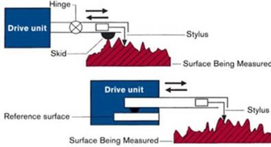
Skidded Proflimeters
Skidded profilometers are used to measure surface roughness of flat surfaces. These kinds of surface roughness testers will use a probe stylus but will also include a small skid (or foot) that moves along with the probe and uses the surface being measured as the reference. In various models, the skid is placed in different positions relative to the probe stylus. Some models have the skid in front, next to or behind the stylus. These kinds of contact surface roughness testers are usually the less expensive of the two types.
Skid-less Profilometers
These contact surface roughness testers will also utilize a probe stylus to measure surface roughness. The difference, however, lies in the fact that these surface roughness testers do not have a skid tracking the movements of the probe. Skid-less profilometers are used to measure cylindered surfaces. For this reason, they are likely to have built-in calculation capabilities that help the machine separate the natural waviness of the object from the surface roughness. This way, the machine is able to deliver very accurate results. These kinds of surface roughness testers are likely to be more expensive than their skidded counterparts.
Choosing Between the Two
The choice between the two largely depends on the kind of surfaces you are measuring among other factors. For example, if a large component of the parts that you are measuring is cylindrical in shape, you are better off using a skid-less surface roughness tester. If you are measuring simple flat surfaces, skidded surface roughness testers can save you some money as they are cheaper.
Whether skidded or skid-less, portable surface roughness testers come with a host of features to help you in your gaging work. These features include the ability to print data on the spot, as well as the ability to connect and transfer data collected to a computer for further analysis and transmission.
Portable surface roughness testers are important tools when it comes to the testing a product’s surface roughness. Surface roughness has important ramifications to the wear and tear of a product as well as its ability to adhere to other surfaces. It is no surprise that many quality testing processes check the surface roughness of products as part of quality testing. For these purposes, a portable surface roughness tester is convenient and can be used at multiple points across a construction site. For a portable surface roughness tester to be really useful to the quality control process, it needs to have the following measuring functions.
Parameters to Look For in a Surface Roughness Tester
Choice of Sampling Length, l, is the nominal wavelength used for separating roughness and waviness. Also known as Cutoff Length or Cutoff. Evaluation Length, L, is the length over which the values of surface parameters are evaluated. It is recommended that the evaluation length consist of five sampling lengths although it may comprise any number of sampling lengths. Also known as Assessment Length. Mean Line, M, is the reference line about which the profile deviations are measured. The mean line of the roughness profile is usually established by analog or digital filters with the selected cutoff corresponding to the roughness sampling length.
Profile Peak is the point of maximum height on a portion of a profile that lies above the mean line and between two intersections of the profile with the mean line Profile Valley is the point of maximum depth on a portion of a profile that lies below the mean line and between two intersections of the profile with the mean line. Profile Irregularity is a profile peak and the adjacent profile valley.
- Roughness Average, Ra, is the arithmetic average of the absolute values of the profile heights over the evaluation length.
- RMS Roughness, Rq, is the root mean square average of the profile heights over the evaluation length
- Maximum Profile Peak Height, Rp, the distance between the highest point of the profile and the mean line within the evaluation length.
- Average Maximum Profile Peak Height, Rpm, is the average of the successive values of Rpi calculated over the evaluation length.
- Maximum Profile Valley Depth, Rv, is the distance between the deepest valley of the profile and the mean line within the evaluation length
- Maximum Height of the Profile, Rt, the vertical distance between the highest and lowest points of the profile within the evaluation length.
- Maximum Heights within a Sampling Length, Rti, the vertical distance between the highest and lowest points of the profile within a sampling length.
- Average Maximum Height of the Profile, Rz, is the average of the successive values of Rti calculated over the evaluation length. This parameter is the same as Rz(DIN) when there are five sampling lengths within the evaluation length.
- Maximum Roughness Depth, Rmax, is the largest of the successive values of Rti calculated over the evaluation length
- Ten Point Height of Irregularities, Rz(ISO), is the average value of the absolute values of the heights of five highest profile peaks and the depths of five deepest valleys within the evaluation length
- Skewness, Rsk, is a measure of the asymmetry of the profile about the mean line. A negative skewness indicates that a greater percentage of the profile is above the mean line and a positive value indicates that a greater percentage is below the mean line
- Peak Density, Pc, is the number of SAE peaks per unit length measured at a specified peak count level. Note: An SAE peak (ANSI/ASME B46.1.1-1995) is a profile irregularity wherein the profile intersects consecutively a lower and upper boundary line.
- Ten Point Height of Irregularities, Rz(ISO), is the average value of the absolute values of the heights of five highest profile peaks and the depths of five deepest valleys within the evaluation
- Third Maximum Peak-to-Valley Height, R3z, is the mean of the third maximum peak-to-valley heights in the evaluation length.
- Core Roughness, Rk, is the core height of the profile along the Yaxis of the BAC curve generated by placing a 40% line on the curve at the minimum slope point and extending the lines to the 0% and 100% points.
- Reduced Peak Height, Rpk, is the height on the Y-axis of a triangle with the same area as the BAC curve from the 0% point to the Mr1 point.
- Reduced Valley Depth, Rvk, is the height on the Y-axis of a triangle with the same area as the BAC curve from the Mr2 point to the 100% point.
- Peak Height, Rpk*, is the distance between the highest profile peak and the intersection line of the surface ratio Mr1.
- Valley Depth, Rvk*, is the distance between the intersection line of the surface ratio Mr2 and the deepest valley.
- Retention Volume, Vo, is the area between the material ratio curve and the 100% material line below the core roughness.
Additional Parameters
- RMS Slope, Dq, is the root mean square average of the rate of change of the profile height calculated over the evaluation length.
- Average Wavelength, la, is the average wavelength of the surface profile.
- RMS Profile Wavelength, lq, is the RMS value of the profile wavelength.
- Height Difference of Bearing Length Ratios, Htp, is the height difference between two points on the bearing ratio curve set at specified levels of tp, tp1 and tp2.
Recalculation
Portable surface roughness testers should be able to recalculate previously collected data for use in other evaluations. This means that the device must have the functionality to take stored data and re-analyze it after changing its previously set profile and roughness parameters.
Varying Evaluation Conditions
Sometimes, quality control staff may like to analyze a set of data under two varying conditions. Portable surface roughness testers need to be able to switch between one set of evaluation condition to another and processes the same data under the two conditions. This saves time and enhances efficiency as the staff does not need to actually run the test twice under two different conditions.
Ability to Measure Narrow Spaces
Portable surface roughness testers need to be able to measure narrow spaces such as the grooves on a piston ring. Portable surface roughness testers can do this by utilizing the narrow part measuring function. This reduces the run-up distance (that the machine needs to start measurement) from the typical 0.5mm to a significantly shorter 0.15mm.
Real Sampling
Portable surface roughness testers need to have the capability to do real sampling by sampling stylus displacement for a set period of time. This takes place without engaging detector traverse. By doing this, the portable surface roughness tester acts as a displacement gage or a vibration meter.
Portable surface roughness testers with the following features or more can make it really easy for quality control analysts to collect, analyze and manipulate data to gain as much information as possible from it.
Some skidless surface roughness testers allow for the following:
Contour Analysis Function
This function allows the portable surface roughness tester to perform contour analysis using data collected during the surface roughness test. This contour data looks at step height, area and coordinate variations within a surface. This is particularly useful when measuring very small objects whose size make it impossible to use a contour measuring device.
Portable surface roughness testers are used in many manufacturing processes to test the quality of the products being produced. The surface roughness of a product has various implications on the use of a product. For example, surface roughness can determine the rate of wear and tear that a manufactured part has. For this reason, it is common for surface roughness to be one of the parameters that quality control (QC) staff measure. Portable surface roughness testers are very handy devices, but their productivity can be greatly enhanced with these useful accessories.
Simple Column Stand
This is a stand that is designed to help raise the portable tester’s height to match the height of the object being measured. This ensures more accurate results and makes it easier to test objects of varying height on the production line.
Tilting Adjustment
The tilting adjustment unit is designed to make it easy for QC staff to align the surface of the part that’s under analysis with the portable surface roughness tester’s reference plane. This particular option works with the column stand.
Auto-Set Unit
This is another accessory that is used in conjunction with the column stand. The auto-set unit allows the vertical axis direction to be automatically positioned. It also allows for single-button operation to automatically measure, save and auto-return. This makes work easier and faster for the QC staff.
Axis Adjustment Table
This accessory makes it possible to make alignment adjustments to measure cylindrical surfaces. The table helps make corrections for pitch and swivel angles. This accessory is also capable of leveling a flat surfaced workpiece.
Analysis Software
This software is can be loaded on to the portable surface roughness tester and allows the machine operators to perform more complex analysis on the device. The software is loaded via a memory card through the memory card port at the back of the device.
Printer
The accessory printer can be connected to the portable surface roughness tester’s digimatic output. When connected, the printer allows the machine operator to do various statistical functions and even draw histograms and D charts. This ability to analyze and present data for comparison purposes makes it easy to draw information from the data for decision making.
Data Analysis Program
Portable surface roughness testers come with a USB port that allows machine operators to take data from the device and transfer it to a computer. If more analysis is needed, there is optional software that makes it possible to translate the data into formats that can be loaded into spreadsheet programs. This way, information collected can be used for presentations or training purposes. It can also be shared on email for further analysis and storage. Related to this is the data wireless communication system that allows the user to share data from the device wirelessly to a computer. When paired with the appropriate software, the accessory will seamlessly help you plug the data into a spreadsheet program for further analysis and sharing.
The various accessories listed above make it easy for quality control staff to use, analyze and share data from their portable surface roughness testers.
You must have heard of terms such as the Ra value when searching for a prototype or machined part. It is a complex term that refers to an industry standard used to specify what the surface roughness of a product design should or should not be. It is extremely important because it can directly affect the performance, functionality, and appearance of the final product. For instance, bearing surfaces must have a uniform pattern of roughness, which is necessary for retaining a film of lubrication. If the pattern of roughness is either too rough, too smooth, or uneven, the bearing will most likely fail.
When it comes to calculating the Ra value, precision and accuracy matter. Note that there is a difference between surface texture and surface roughness. Surface texture is often used to determine surface roughness as explained below.
How Is Surface Texture Measured?
Surface texture can be measured in several ways. The ideal option often depends on factors such as part material, size, or geometry. There is for instance, the probe or stylus method which is one of the most popular methods of measuring surface texture. The stylus of the probe used for measurement is known as a surfometer. It is gently drawn across the surface or face of a part. Even the slightest deviation from a reference or nominal line is recorded on a clear graph for analysis and interpretation. Surface roughness can then be calculated from the readings.
Optical Photometry
Once the value of the surface texture has been calculated and used to determine the Ra value, photometry steps in. It is simply a way of looking at the total surface area of a part from a wider view to determine if there are other surface defects.
Optical photometry is also handy when it comes to identifying asperities. These are inclusions, voids, and scratches that are sometimes found in raw materials. In other words, they are contaminants. Most mathematically derived models discount these anomalies as subtle and irrelevant. The presence of even a slight defect in critical applications, scientific instruments, or products from the aerospace/defense industry can prove to be catastrophic. That explains why the use of mathematically derived models to measure asperities is becoming increasingly unpopular. Precision and accuracy are everything when it comes to measuring surface roughness.
Does it Matter?
Yes, surface roughness matters if you not only want a perfect prototype but a perfect finished product as well. Remember that surface texture alone is one of the main areas where clients and factors disagree. That’s because it is often difficult to specify. That is why it is a good idea to first discuss this specific design aspect in detail just to clear doubts before commencing with a quotation or production. Keep in mind that there are many different and reliable ways to finish a surface, and to come up with appealing mechanical and aesthetic effects. With that in mind, explore all of your options before deciding on the best one.
The problem with any gage functioning as intended has to do with the cleanliness of the parts. Residual oil or machining swarf though extremely small, can simply interfere with parts passing thru the gage.
If a part has any contamination and is at the high end of the tolerance range, any bit of dirt or even too much oil, the part will not enter. Sometimes if the part is aluminum, galling will occur once the high polished surface finish is worn or burnished. This galling or sticking of material on the ring gage surface can be removed by re-lapping the gage with extremely fine compound, a cotton bob with lapping compound, will generally suffice.
Carbide and ceramic generally wear the same, that is about 20 times longer than steel, depending on the material being gaged and the cleanliness of the parts. It all comes back to the cleanliness of the parts.
ceramic gages generally wear the same as carbide gages which is about 20 times longer than steel. Depending on the material being gaged and the cleanliness of the parts the wear life can vary. It all comes back to the cleanliness of the parts. Ceramic is generally viewed as “fragile”, therefore it is to be handled with more care.