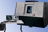
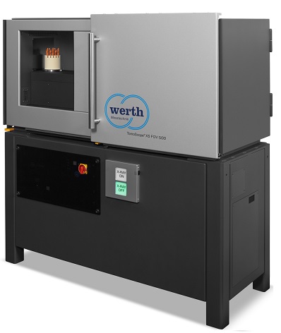
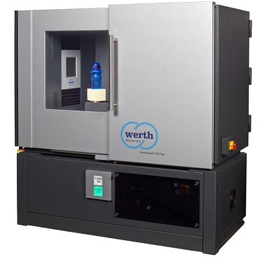
TomoScope® S CT Scanner

TomoScope® S CT Scanner.

call 866-945-5742 or email [email protected] for more info

Read More

TomoScope® S CT Scanner Features

  • Multisensor coordinate measuring machine for 3D  measuusing the principle of Computed Tomography, in combination with additional sensors (tactile sensor systems, optical sensors)
  • Robust granite base with integrated air bearing rotary axis
  • Optional second Z-axis for collision-free operation in multisensor mode
  • In both design and construction, the measuring machine meets the legal requirements for a fully protective device according to x-ray device regulations. Additional safety features have been included over and above the legal requirements.
  • Modular structure guarantees customized solutions for individual applications
  • Grid tomography to extend the measurement area (optional)
  • Micro focus X-ray source up to 225 kV
  • Measuring Range
    • Ø=204 mm(8) (in the image)
    • Ø =204 mm(8) (using raster tomography)
    • L=213 mm(8.4) (in the image)
    • L=398 mm(15.6) (using raster tomography)
  • Foot Print and Specification
    • Depth: 1135 (44.7”³) Width: 2120 mm (83.5) Height: 1713mm (67.4

TomoScope S

COMPUTER TOMOGRAPHY – MULTISENSOR COORDINATE MEASURING MACHINES WITH X-RAY TOMOGRAPHY-1

COMPUTER TOMOGRAPHY

The base of the machine frame is of solid granite design. Other system components, such as scales, linear and rotary axes, drives, and guide components come from the family of coordinate measuring machines described above. Using this construction, calibration data such as magnification, rotary axis position and geometric corrections are stable over long periods.

The basic machine construction is shown in Figure 37. The linear axes serve to adjust the magnification of the X-ray sensors for rasterizing during tomography and for classic measurement with tactile and optical sensors. For the latter task, the various sensors and associated probe changer already described can be used. In order to ensure crash-free operation, the X-ray sensors and the other sensors are mounted on separate Z-axes.

COMPUTER TOMOGRAPHY – MEASURING A PLASTIC PART

COMPUTER TOMOGRAPHY

The process for measuring a workpiece using a TomoScope® is shown in Figure 44. The measured object is located on the rotary table. During the tomography process, many 2-D radiographic images are taken. The part rotates once through 360 degrees. The 3-D voxel image is available as an intermediate result, which can be used for 2-D slice analyses or embedded material and air void inspections and similar tasks. The measurement points obtained from the voxel data are geometrically corrected using the “autocorrection feature and compared to the CAD model. Deviations are shown graphically in various colors. In addition, features such as lengths, angles, diameters, and position tolerances are evaluated

The measurement process described above is particularly cost-effective, for example, for first piece inspection of plastic molded parts. Inspections that previously required several days to verify multicavity molds are reduced to a few hours. The measurement results can be imported directly to generate corrected CAD data for mold rework by using the “Mold Correction function in the WinWerth® software. Similar advantages result for sample measurement inspections. The same method can also be used in a similar form for other materials and production processes.

WINWERTH® 8.40 – THE TACTILE AND OPTICAL INTERFACE OF CHOICE

WINWERTH® 8.40

The new version 8.40 of WinWerth® has a number of additional functions. The expansion of scan path and point distribution modes to cover all standard geometric elements eliminates the need for time-consuming manual positioning of the sensor. The risk of collision is minimal, as WinWerth® detects obstacles on the work piece and generates travel paths to avoid them. Using feature-oriented measurement, individual dimensions can be selected out of an extensive measurement program. The user selects the desired features and WinWerth® automatically identifies the alignment of the work piece and all of the relevant elements with their associated settings.

Several new functions are available for TomoScope® and TomoCheck machines as well. For example, the volumetric capacity of a container or the volume of a work piece can be calculated. Using the void filter, computed tomography measurements (CT) can be analyzed without the detrimental influence of voids – or the voids can be sorted by size and displayed and analyzed separately. Multi-Spectra-Tomography provides a unique solution for multi-component work pieces such as assembled plug connectors.

The new AutoAlign function automatically recognizes the work piece in a rastered image and aligns it to a reference element using a best-fit algorithm. The new HD raster scanning can be used to capture large areas at high structural resolution automatically. Displaying sensor travel paths in the 3D graphics window makes it easier to quickly check the measurement sequence and reduces measurement time by optimizing the travel paths.

INCREASED EFFICIENCY FOR HIGH-RESOLUTION MEASUREMENTS

INCREASED EFFICIENCY FOR HIGH

Region of Interest (ROI) tomography was developed to create high-resolution images of some regions of larger work pieces. In the past, the entire work pieces always had to be fully scanned at high resolution. ROI-CT only measures the relevant area at high magnification. To accomplish this, the entire work piece is first captured at low resolution and the desired partial region (ROI) is captured at an appropriately high resolution. This can improve measurement time and reduce the resulting file size.

With conventional ROI tomography, ROI zones needed to be in the exact center of the rotary axis, greatly limiting both the flexibility and number of possible regions of interest. The new, function of Eccentric computed tomography (CT) now makes it possible to place the work piece arbitrarily on the rotary table. This eliminates the laborious and time-consuming alignment of the workpiece, making measurements more convenient and efficient. The WinWerth® software automatically calculates a virtual axis of rotation at the center point defined by the operator within the measured volume. During the measurement, rotation about the virtual axis of rotation is ensured by moving the precise machine axes.

The Multi-ROI-CT option combines the advantages of Eccentric and ROI tomography. The high-resolution regions of the work piece can be located at any arbitrary position within the measured object. Several ROI zones can even be captured and linked together. The overall volume and the ROI volume are located within the same coordinate system. This means that an overall point cloud for the work piece can be computed automatically with different structural resolutions. During analysis, features from the overview volume and the various ROI measurements can be linked to each other. This unique combination of Eccentric CT and ROI CT makes computed tomography an economically feasible solution for an even greater range of applications.


help desk software