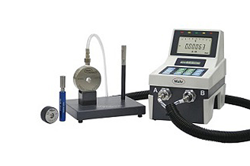
Air gaging is a common technique used in a wide range of manufacturing process. Technicians that work on the shop floor often utilize air gages due to the advantage that the product offers. Air gages are not only easy to use and fast, they can measure to very tight tolerances (down to a resolution of 5-50 millionths!) and even clean the part’s surface before measuring. When it comes to air gaging, most gage users automatically think of air plugs. There are, however, various styles of air forks and air rings. These tools provide similar benefits and a few additional ones too.
The Low-Down on Air Forks
In some cases, you can’t simply place a part in an air ring, e.g. on crankshafts. There are just too many journals and some of them have very tight tolerances. This means that there is no way to place an air ring over this area. This is when you will need an air fork.
You do not get air forks simply by slicing an air ring in half. There are some critical dimensions to consider. In addition, they come with precision-ground locating stops that are found at the back. These features allow the operator to create the reference based on the known part diameter and position the jets with precision.
Maximizing the Capabilities of Air Forks
You can get the air forks to really shine if it’s possible to customize the position of the air jets. For example, you can measure a diameter right up to a face by placing the jets near the end of the fork. Alternatively, you can also add multiple jets to measure up to three diameters simultaneously. You should be able to read the three diameters as one without a lot of computing power. Don’t forget to calculate shape and taper as well.
If you are measuring challenging outer diameters, it is a good idea to remove the mechanical snap or the bench stand and consider leveraging air.
The Low-Down on Air Rings
Air rings are the opposite of air plugs. They are typically utilized to measure outer diameters. These rings often have a basic design, e.g. a steel ring and a pair of jets attached to a particular location. Surprisingly, a lot of engineering is built into them.
If you need to calculate the size of the ring, ensure that you achieve a proper balance of clearance between the opening in the ring and the part. If there is too much clearance (it will measure a chord rather than the diameter), your readout will display a centralizing error. If you lack clearance, a geometry error can occur. In this case, you won’t be able to insert the part into the air tool.
You should check and ensure that the jets are positioned slightly lower than the body of the ring. It provides the air system with the correct differential characteristics to function properly. Additionally, it allows for ring wear.
Diameter Measurements with Air Rings
When it comes to measuring basic diameters, two-jet air rings will suffice. Gears and pullies, however, feature multiple ODs. In most cases, you will need to measure the diameter right up to the face where your rings are attached to. You will need to get a snout-type or shoulder-type air ring. They are basically blind hole rings that allow you to position the jets closely to the face and measure the outer diameter right to its end. Snout type rings can get around obstacles and clearances more efficiently. It is useful to note that air rings may be designed with between three and six jets.


