Automate in 2024 | Boost ROI + Alleviate Bottlenecks

Are bottlenecks causing delays in your QC process?

By automating your QC process, you can alleviate bottlenecks and improve efficiency. At Willrich Precision Instrument, a dedicated metrology house with over 51 years of experience, we understand the importance of automation in streamlining your QC process.

www.willrich.com

Why should you automate your QC process?

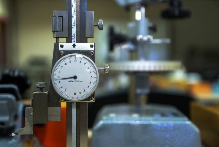
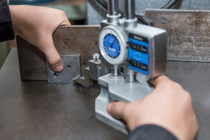
Manual gauging is labor-intensive and can significantly slow down production. Additionally, being understaffed or relying on outdated processes and slow equipment like a CMM can further hinder your operations.

Automating manual gauging can help reduce or even eliminate bottlenecks in manufacturing processes. In-process manual gauging can slow down machine cycles and result in idle spindle time, affecting machine output. Automated gauging systems can streamline this process and ensure accurate measurements. In the case of incoming inspection, an automated gauging system can help avoid delays and bottlenecks caused by limited resources and the need for inspection of outsourced parts.

Is automation worth the investment?

It is definitely worth the investment, as it offers numerous benefits that can be quantified with a return on investment (ROI) calculation.

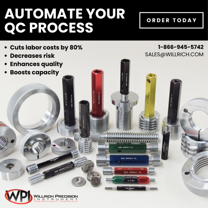
By automating manual gauging processes in manufacturing, companies can experience reduced labor costs, decreased risk, higher levels of quality, and increased capacity. A practical example demonstrates how automation can lead to significant cost savings. For instance, if a medical device manufacturer employs two full-time QC inspectors to measure small parts manually, it costs them $3,360 per week in labor. However, by implementing automation technology, the labor cost for part measurement can be reduced by at least 80%, resulting in savings of $2,688 per week.

With the estimated implementation cost of $125,000, the full payback period for this investment is under a year. Beyond the payback period, the ROI is significant. Over three years, the investment can result in a 300% return, paying for itself three times over.

At Willrich Precision, we offer a wide range of metrology products, from sophisticated scanners to basic measuring tools, ensuring that we have the right solution for your dimensional inspection needs.

Don’t let bottlenecks hold you back. Automate your QC process with Willrich Precision Instrument and experience the benefits of increased efficiency and improved ROI.

Visit our website and explore our comprehensive range of solutions today!

Top Mistakes To Avoid When Using Thread Gauges

thread gauges

Thread gauges are used for a wide variety of industrial operations and can be considered as equipment that is essential. As an owner of a thread gage, it is important to note that maintenance is necessary in prolonging its lifespan and productivity. However, it is very common for serious mistakes to be made when using this type of gage that can affect the efficiency and condition of the equipment. Ensuring that you avoid these mistakes can help you to prevent any malfunctions of your thread gage. Here at Willrich Precision Instruments, we provide a wide variety of different precision instruments that are made with the finest materials and guaranteed to withstand the test of time.

Exposure to Temperature Extremes when Storing Your Thread Gauges

Obviously, as a precision instrument, the most important thing to maintain in a thread gage is its precision. These gauges are made using metals that can be sensitive to temperature and can either expand or contract depending on the extremes. This change in size of the thread gage can compromise the precision of the thread gage. Thus, you should only store your gauges in a storage area that is not affected by the extreme temperatures as the result of the climate. Additionally, make your best effort to store your gauges in a place where there is as little humidity as possible in order to prevent rust from ruining the quality of its performance.

Allowing Your Thread Gauges to Become Dirty

The dirt that gets trapped in between the parts of your thread gage can negatively affect its functionality and can decrease the precision of the instrument. Therefore, it makes sense to schedule regular cleaning of your thread gage so that proper maintenance of the parts is carried out. Additionally, in the industrial environment, workers’ hands can become contaminated with oil or other substances that can affect the performance of the gauges as well. As such, thread gage operators should be trained to clean their hands before touching the gauges so as to prolong the life and increase the efficiency.

Failing to Lubricate Your Thread Gauges Adequately

Lubricating your thread gage is essential in preventing any corrosion of the parts. This also ensures that the entire system works seamlessly. What you can use for lubricating your thread gage includes oil-based easy-peel wax coatings.

Not Keeping Track of the Accuracy of Your Thread Gauges

It is inevitable and only natural that your gauges become less accurate over time. This would require you to regularly recalibrate the thread gage and document the changes of its accuracy. Ensure that the dates which you carry out the recalibration are documented properly and that the schedule is in line with the recommendations of the manufacturer.

Not Training Your Thread Gage Operators

The easiest way to make sure that your thread gauges are treated and used in the right way is to give your employees who operate the thread gauges proper training. The training should encompass how to use the equipment and also how to engage in proper maintenance so that it can stay efficient for years to come.

Whenever you have new employees, it is always wise to give them proper training as to what the right storage methods and maintenance procedures are. Be sure to hand out manufacturer manuals so that they can learn how to avoid malfunctions and engage in proper safety procedures as well.

Choosing The Right Hardness Tester For Your Needs

hardness tester

Hardness testers are essentially devices that can accurately tell you the hardness of a certain material. This is done by taking into account the effect that an indenter (usually made from hard steel or diamond) has on the surface of the material. The depth of the penetration into the material is measured and from this the hardness can be taken. Here at Willrich Precision Instrument, we understand the difficulties one might face when choosing a hardness tester because of how many different types, brands and models there are in the current market. We specialize in hardness testers and other high-quality metrology instruments that can suit the industrial needs of all our clients.

The Different Kinds of Hardness Testers

In the current market, there are two main types of hardness testers. They can either be bench hardness testers, also known as stationary or classical hardness testers. On the other hand, they can be portable hardness testers, more commonly known as mobile or electronic hardness testers.

Bench Hardness Testers

As the name suggests, this is a very classic hardness tester that can measure the hardness of materials using traditional methods such as Brinell, Vickery or Rockwell. Usually, when you are looking for a hardness tester that uses the Vickery method for example, it will be called a “Vickery bench hardness tester”. As the word “bench” suggests, there are also some bench top hardness testers in the market that can allow the user to measure the hardness by a few different hardness scales. There are actually some hardness testers that can measure with a combination of scales. All bench top units are big in size and can be very heavy, with some models being over 50 kilograms. They have to be mounted on a table or the floor, which allows for easy measurements using the direct method.

Portable Hardness Testers

In contrast to the bench hardness testers as mentioned above, portable hardness testers are obviously much smaller in size. They are also much lighter in weight. Additionally, being much more compact than bench hardness testers, they can measure the hardness of your materials with some scale violence. There are several advantages to using portable hardness testers. For example, you can bring the device with you easily from home to the workshop to measure the materials that you want to test.

Portable Hardness Measuring Instruments

These are also portable like the testers, but the main difference is that they are electronic devices. What this means is that there is usually a larger range of features that you might not get with an analog device. For example, you will be able to save the results on the device’s internal memory. This would greatly increase the convenience for users because the measurement results can then be transferred to a computer so that reports can be created. The reports can be created using specialized ARM control programs that are more common in portable hardness testers. However, there are very rare cases where some tests can only be carried out by bench hardness testers. In all other cases, portable hardness testers work just fine.

Why Hardness Testing Is Essential

The hardness of a material is its inherent property that allows it to withstand abrasion, bending, scratching, cutting or deformation. If your day to day work involves materials manufacturing, you are most likely aware of the importance of a hardness test in allowing you to evaluate the products received from external suppliers and also, the production process of internally manufactured products.

Baseline measurements have to be defined and set in place in order to make sure that your products meet the required quality specifications in terms of strength. However, if you are new to the field, you might be unaware that the hardness of any material is not an intrinsic property but rather, the value obtained from a hardness test stems from a specific measurement sequence. Read on to find out more about hardness testing and how it can be performed!

Types Of Hardness Testing

For many materials in the 21st century, a hardness test comprises of using a device that impacts the material with a defined amount of force over a specific amount of time before measuring the depth of the groove left behind. The commonly used hardness tests that measures the relationship between hardness and the depth of the indentation can be classified into the Rockwell, Brinell and Vickers hardness test.

Rockwell Hardness Test

Rockwell hardness tests is one of the most commonly used hardness tests in the market due to its fast speed and high accuracy in determining the hardness of numerous materials such as metals, plastics and allows. When conducting this test, a hardened steel ball indenter or a diamond cone would be pushed into the material with a test force of 10kgf. Upon attaining equilibrium, more force would be used in order to cause a greater indentation depth. Once equilibrium is reached again, the force is removed, and the permanent depth of the indentation made would be used to determine the Rockwell hardness number of the material.

Additional Benefits Of Hardness Testing

By conducting a hardness test, the results obtained can be used to predict and determine the extent whereby the tested material can perform under various conditions. For example, by measuring the hardness at various temperature and humidity conditions can simulate and allow you to know if the hardness of the material would be impacted by storing it in a humid warehouse. If the hardness measurements remained constant, it indicates that the material can be stored normally. Otherwise, special precautions must then be taken to ensure proper storage of the material. Another instance would be testing the material’s hardness under prolonged exposure to various chemicals. This would allow you to determine the material’s resistance to chemicals and if special caution needs to be taken to ensure the functionality of the material is not affected by a chemical exposure.

Conclusion

All in all, a hardness test is a crucial test that you must adopt in ensuring that your product meets the stated quality specifications.

At Willrich Precision Instrument, we provide a large selection of hardness testers that would definitely meet the rigorous needs of your business! Browse through our exciting inventory and shop for quality surface roughness testers today. If you need assistance with any product purchase, call us at 866-945-5742 or email us at [email protected] today.

Understanding Bore Gages

A bore gage is an instrument that is frequently used to measure the internal of a hole. It is also known by many names such as bore mics, hole tests, holtests, internal micrometers or cylinder tests depending on your geographical region. It operates on the basis whereby parts known as the anvils expanding outward in order to determine its diameter when inserted into the hole. Read on to find out more about the characteristics and uses of bore gages.

Types Of Bore Gages

There are numerous types of bore gages in the market, with the more common types being bore gages with two or three anvils respectively. Bore gages with two anvils are cheaper and are calibrated with gauge blocks whereas those with three anvils are known as internal micrometers and are calibrated with setting rings. Both types can make use of either a digital or dial scale to display the measured diameter of the hole. Apart from the common bore gages, there are also more specific types specializing in various measurements, such as the dial bore gages, small hole gages and telescopic bore gages.

Sizes Of Bore Gages

Depending on the diameter of the hole that you are measuring, you would require different types of bore gauges that have various measurement sizes. If you are looking for a bore gage that can measure a wide range of sizes, an adjustable bore gage would be the equipment that is suited for your needs! However, this type of gage suffers from a lower tolerance in the measured diameter. If a high degree of accuracy is demanded in the final product, plug gages, which comes in fixed sizes would be the equipment that you have been looking for. Plug gages can be customized accordingly to your requirements, making them available in both small and large sizes.

Uses Of Bore Gages

With the high level of precision obtainable in a bore gage, there are many applications where it can be used such as the measurement of pipes, holes and cylinders, which are commonplace in the manufacturing, automotive and equipment calibration industries. Inspectors and maintenance staffs utilize bore gages to inspect the dimensions inside injection moldings to ensure that its quality are up to the desired standards, or in extruder barrels to monitor wear and tear over an extended period of time to find out when preventive maintenance can be carried out. Mechanics and machinists also make use of these equipment to detect the extent of wear and tear in cylinder heads and also to accurately measure holes in an engine block to ensure that the pistons fit tightly to prevent any gas leakages.

Conclusion

With the numerous potential applications of bore gages and its ease of customizability in terms of types and sizes, it serves as a handy tool that can greatly assist you in the measurement of a hole’s internal diameter.
At Willrich Precision Instrument, we provide a wide range of bore gages that would definitely meet the rigorous needs of your business! Browse through our exciting inventory and shop for quality bore gages today. If you need assistance with any product purchase, call us at 866-945-5742 or email us at [email protected] today.

A Short Course On Measuring Pitch Diameters

Do you know that bolts, tapes, dies and other helically threaded components are characterized by various parameters? These parameters include depth, angle, pitch, major and minor diameters, whereby the pitch diameter holds the most significance amongst these parameters. Read on to find out more about the importance and the process of measuring pitch diameters!

What is a Pitch Diameter?

To many of us, the effective diameter, also known as the pitch diameter, refers to the diameter of the cylinder as it cuts the midpoint of both the major and minor diameters known as the pitch line. The pitch diameter is an important property that governs the compatibility between two threaded parts, such as nuts and bolts and if they can be successfully mated with each other. Moreover, they are also used as a crucial reference for other relevant thread measurements.

Measurement of Pitch Diameter

Due to the large susceptibility of pitch diameters to measurement errors, unique measuring equipment must be used in order to obtain an accurate reading. Although there exist many types of techniques to measure pitch diameter, there exist three most commonly utilized methods, namely the three-wire measurement method, the optical comparators and specialized micrometer screw gages which ensures the accuracy of your reading!

Three-Wire Method

The three-wire method makes use of a traditional, flat anvil micrometer screw gage to measure pitch diameter. Three separate wires of pre-measured diameter would be placed within the pitch of the threads before the gage of the wire is chosen. This enables the wires to stay in contact with the pitch line while simultaneously extending beyond the outside diameter of the thread. With another micrometer screw gage, the distance between the wires on the opposite sides are measured and used as inputs in prescribed formulas to derive the pitch diameter.

Optical Comparators

Optical comparators make use of the fundamental basis of optics and light to determine the pitch diameter. A magnified silhouette of the threaded object is projected on a screen and a specialized software would be used for image analysis and to obtain the pitch diameter. Through the use of optical comparators, it would result in a high degree of accuracy in pitch diameter measurements. However, a downside of it would be its expensive cost!

Specialized Micrometer Screw Gages

A commonly used instrument would be a form of micrometer screw gage known as a thread mic or a pitch mic. It was designed for the purpose of measuring the pitch diameters of cutting threading tools. To make use of this instrument, the ratchet of the micrometer is turned continuously until the spindle comes into contact with the thread flanks. The pitch diameter can then be read off from the micrometer scales. This method provides an efficient and accurate, but yet a low-cost way of measuring the pitch diameter!

At Willrich Precision Instrument, we provide a large selection of thread gages that would definitely meet the rigorous needs of your business! Browse through our exciting inventory and shop for quality thread gages today. If you need assistance with any product purchase, call us at 866-945-5742 or email us at [email protected] today.

A Guide To Measuring Surface Finishes

The finish, or surface texture of a finished component can be viewed differently from two different perspectives. For the designer, variations of surface texture would affect the functionality of the component. If the designer wishes to change the component’s functionality, the surface texture specification must be altered. From the machinist’s point of view, the finish is the end product of the manufacturing process and it can be altered by modifying the manufacturing process. Read on to find out more about measuring surface finishes and the various parameters involved!

Variations In Surface Finishes

Surface finishes contains the troughs and crests that comprises the surface and the direction of the surface. Through the usual machining processes such as grinding, milling and turning, uneven sections are being imparted onto the component’s surface. Moreover, other factors such as the vibration, speeds, condition of the machine tool and the choice of machine tool can also affect the extent of these irregularities. As a result, these factors must be carefully controlled.

Components Of Surface Finishes

Surface finishes can essentially be classified into 3 segments:

  • Roughness: Roughness stems from the usage of cutting tool that leaves a mark with a distinct depth and width. Also, in the cases of grinding, the abrasive granules on the wheel can also leave a groove on the surface of the component that is being produced.
  • Form: Form can be attributed to a lack of straightness or flatness in the machine’s cutting tool, resulting in the component’s surface finish being affected. This results in a systemic deviation from the specified requirements whenever the machine is being used.  
  • Waviness: Waviness of a component is defined as small variations in the length between the cutting tool and the produced component during the manufacturing process. These variations are caused by the instability of a cutting tool due to vibrations. The source of vibrations can be internal such as the motor of the machine or even externally induced due to the operations of other machines nearby. The waviness of the component can be measured by a contour measurement device.

How To Measure Surface Finishes

All of the above-mentioned surface finish components exist simultaneously and each condition is checked
separately. By measuring these components, the search for the origins of the error can be narrowed, allowing its effects to be reduced or eliminated. There are many instruments available in the market that would enable you to measure these 3 components, such as a pocket-sized, battery-powered gages. Its low price allows for the measurement of a small number of roughness parameters at an affordable cost. Furthermore, these instruments are also very flexible and are very easy to use. If you require more complex parameters to be measured, more precise equipment but expensive that involves powerful computers would be required!

At Willrich Precision Instrument, we provide a large selection of surface roughness testers and form measurement that would definitely meet the rigorous needs of your business! Browse through our exciting inventory and shop for quality surface roughness testers today. If you need assistance with any product purchase, call us at 866-945-5742 or email us at [email protected] today.

Top Tips To Facilitate Rockwell Hardness Tests

hardness test

Hardness is defined as the measure of resistance that a material has when force is applied to it. Others may refer to hardness as the ability of a substance to resist scratching, cutting or abrasions. There is a direct relationship between the level of hardness of an object and the level of its resistance. The greater the hardness, the greater the resistance. Hardness is largely determined by a substance’s microstructure. Hardness matters because it gives us an indication of how the material will stand up against pressure. This has implications on how the material can be used and what kind of pressure it can withstand. For this reason, measuring hardness is a routine procedure in most quality control processes. Here are some of the ways of facilitating Rockwell hardness tests.

Check Indenter

Before carrying out a Rockwell hardness test, it is critical to ensure that there is no chipped or cracked diamonds on the indenter. This is because any of such anomalies are likely to lead to errors in the readings. Experts recommend checking the indenter every week with a magnifying device (such as a Jeweler’s eye loop). However, it might be hard to tell if the indenter is damaged. For this reason, if you notice consistent erroneous readings, this might be another clue that there is a problem with the indenter.

Verify Hardness Readings

Before performing a test, experts recommend that you test the hardness of a test block. This is a block with a hardness that is already known and thus the idea is to check if the reading from the tool is consistent with the known hardness. It is usually standard to do at least three tests in order to establish a consistent reading. It is also standard to discard the first reading after an indenter or an anvil change.

Keep the Rockwell Hardness Tester Clean

Debris, dirt and other contaminants can affect readings. It is important to remove and clean the indenter and anvil before you start testing. It is also critical to do this at every break between the shifts so that all parts of the tester stay clean throughout the day.

 Smoothen Surfaces

When testing objects that are rough or that have textured surfaces, it is important to be aware that these kinds of surfaces can affect the readings obtained from the tester. To help overcome these kinds of problems, ensure that you lightly sand the surface to reduce the roughness.

Watch out For Movement

If you get any movement of the part while doing a test, you should discard the reading and perform another test. You should also avoid including these readings in your final average. This is because the movement of the part can affect the accuracy of the test.

Watch out for the Edge

When you take readings very close to the edge, it might cause problems with the reading and might even damage the indenter. Ensure that all readings are made at least 2.5 times the diameter of the indenter from the edge. The key to note is that if the metal buckles outward, then you have positioned the indenter too close to the edge.

Top Tips To Choose A Film Thickness Gage

thickness gage performance

A film thickness gage is one of the most essential instruments used in the coatings industry today. Errors in film thickness estimates lead to a significant waste of money, material and time. If a coating application makes a dry film excessively thick, this leads to failures such as flaking, cracking or excessive drying time. In the event that a film is excessively thin, its protective capabilities and hiding power become inadequate and time is lost by having to recoat the entire surface. 

For these reasons, it is important you know how to properly select a film thickness gage. Below are some key factors you can consider when choosing a film thickness gage:

Film Thickness Gage Performance

When choosing this type of thickness gage, always keep in mind its level of performance. A good question to ask yourself is how precise or accurate you need it to be. A high performance gage is needed if you are applying less than 1.0 mil of dry paint film. If you want to further improve your accuracy, choose one which has single or a two point calibration feature. Remember, the gage can be calibrated in line with certified film thickness standards. 

Substrate 

Always consider the substrate the coating is being applied to when choosing a thickness gage. Is the substrate metal or non-metal? If it is metallic, the metal is either ferrous, such as steel, or non-ferrous, such as aluminum. It is worth noting that ferrous metals have magnetic properties, unlike their counterparts, the non-ferrous metals. 

ISO Compliance 

You might be required to document your measurements for ISO compliance. In this case, a film thickness gage with computer interface capabilities and memory is your best choice.

Measurement Area

Another important factor to consider when choosing a film thickness gage is the measurement area location. You will need an exterior probe sensor when measuring inside corners, pipes, and very small surfaces. Unfortunately, when external probe sensors come into play, the choice of film thickness gage models becomes quite limited. 

Certified Thickness Standards

It is recommended you get a certified thickness standard to check if the gage is performing as required. 

Bottom Line

Before choosing a film thickness gage, there are some important factors you should have in mind. For effective coating to take place, you need a well measured film thickness gage. 

Willrich Precision Instrument offers a wide range of film thickness gages that can meet all your gaging and inspection needs. We are an ISO certified company and have been the premier provider of precision measurement systems for over four decades. Our staff is knowledgeable and ready to help you with any questions you may have regarding your metrology needs. Feel free to contact us to discover more about the products and services we offer.

Understanding Height Gage Measurement Procedures

Height Gage Measurement Procedures

Height gages are useful instruments when one needs to measure the height of an object. They come in many different forms and modern height gages can also be used to measure internal diameters among other things. Electronic height gages can be very precise and often claim a consistency of ±0.0001in. Height gage measurement typically involves a moving arm with a pointed end that is usually in contact with the object that is being measured. In the old gages, readings were taken off a vertical and calibrated shaft. Modern height gages have a digital display where readings are displayed.

In recent
years, digital height gages have become the preferred choice in many machining
shops. They are made with hardened stainless steel and a heavy base. This makes
the instrument stable and ensures that any reading made are accurate. Digital
height gages also come with data ports that allow the machine operator to
transfer data from the gage to a computer. From there, the data can be printed
or stored for later use.

Preparing
the Gage for Use

It is
wise to start the process by cleaning the bench from which you are working. Any
objects or particles on the surface can affect the stability of the height gage
and in turn affect the accuracy of the readings. To get the best results from
your height gage, always ensure that the base of the gage is resting flat on
the surface of the workbench.

Once
that is done, dry the sticker on the digital height gage and fix the measuring
arm on the gage after cleaning it. At this point, ensure that all the LCD displays
and controls of the height gage are working flawlessly. You should also clean
the surface of the item you are measuring with a cloth to ensure that there are
no impurities on the surface of the object.

Using
the Gage

When
it comes to taking measurements, move the measuring jaw so that it gently
touches the platform surface. If the machine is set correctly, the value on the
display should be zero. If it is not, turn the machine on and off until it is
zero. When this is done, keep the rod against the surface and move the
measuring jaw to the closest reading. When this is done, take the reading on
the LCD screen.

Things
to Note

If you
have an object that is above the range of the height gage, raise the base of
the gage and place an even block underneath it. Zero-point becomes the platform
surface and the starting point is the top of the block. In such a case, ensure
that you have preset the height of the block. Remember to clean the jaws and the
unit after measurement before storage. You should also avoid applying electric
current to any part of the unit as this is likely to damage the sensitive
electronics in the unit.

If you are looking for high-quality height gages for your machining processes, Willrich Precision Instruments has exactly what you need. We believe in not just supplying high-quality precision instruments but in building strong partnerships with our clients. This way, we are always there when you need us for calibration services and any other kinds of support.

What Is The Proper Way To Read Height Gages?

Read height gages

Height gages allow a machine operator to measure the depth of an object with pin-point accuracy. These gages differ immensely from model to model but most have the same basic structure. They consist of an arm that is usually in contact with the object being measured and a measuring unit that moves up and down the scale. Height gages typically measure vertical spaces but can also measure other dimensions such as internal and external diameters. Ever wondered about the proper way to read height gages? Read on to find out more:

Vernier Height Gages

The
first step when using this kind of height gage is to lock the arm into position
after placing it at the top of the object being measured. When this is done,
you need to then find the ‘zero” on the vernier scale that goes along with the
moving part on the scale. Look at the number on the upright shaft that falls
across the zero marking. Take note of this number as it is the first portion of
your measurement. When this is done, look at the numbered line on the vertical
scale that best aligns with a line on the vertical shaft. This number becomes
your final portion of measurement. The final step is to combine the zero
measurements with the best-aligned measurement to get the final height
measurement of the object you are measuring.

Dial Height Gages

Start
with positioning that arm in place at the top of the object that you want to
measure. When this is done, take note of the last number located beneath the
measuring equipment on the shaft. These numbers are likely to be in increments
of 0.1 inches. Take note of the number that the needle is indicating on the
dial face. The final step is to combine the measurement that you took on the
vertical shaft with the measurement that you noted from the dial face. The
combined number that you get represents that height of the object that you are
measuring.

Digital Height Gages

When taking measurements using this type of height gage, place the arm in position at the top of the object that you wish to measure. When this is done, find the digital display on the height gage and take note of the number that is shown on the display. This number is the height of the object that you are measuring. With digital height gages, you do not have to take the ‘zero’ setting as this is automatically set by the gage when you switch it on. For this reason, digital height gages are very popular as they can give readings much faster than the other two. This ability is critical in a manufacturing process where the quality control officers have to randomly test samples from the production line without slowing down the production process.

Looking
for high-quality height gages? Willrich Precision Instruments has been
providing clients with the best precision instruments for over four decades. We
are a one-stop-shop for all your precision instrument needs.

How to Make the Most Out of Your Height Gages

height gages

Height gages are used to measure a lot more than just heights. These useful measuring tools trace their origins back to the 16th century when Pierre Vernier developed the vernier scale. This scale allowed mathematicians and engineers to measure accurately. So good was his system that the scale became the standard of quality measurements for the next four centuries. From this, the vernier height gage and the gear tooth vernier height gage were developed and became widely used throughout various industries.

The height gage as since come a long way and a lot of other useful functionalities have been added to it. Its basic design has not changed much though. It looks like a hand-held caliper that rests on a heavy base that keeps the tool aligned to the surface. In the original machines, the scale had a movable jaw that was used to mark a part to indicate a measurement. Here is how to get the most out of your height gage.

Setting it Up

Before you can use your height gage, you will need to set two references. The first of those is the zero-reference which the tool is able to set automatically. It does so by moving to touch the surface to set a reference point. Machining experts recommend that you do this process twice so as to ensure that no dirt or other anomalies interfere with the reference.  The other point of reference is correcting for probe ball diameter. This reference does not matter very much if the gage is only being used to measure heights. 

If, however, the gage will be used to measure grooves or diameters, then it is important to take the probe ball diameter into account. For most modern height gages, the probe ball diameter is measured automatically and its dimensions automatically factored into all readings. The machine takes a fixture that comes with the gage which sets up a plane. This plane is measured from the two opposing directions and the difference between the two measurements is taken as the ball diameter.

How to Measure

Modern digital height gages make it easy to take any measurement. All the operator needs to do is to slide the measuring carriage across the part that is being measured and press a button. The gage will move the carriage from the top to the surface and print out the height reading on the display. Modern height gages allow the operator to manipulate and share data. They come with data ports and other useful connectivity options that allow for the transfer of data to computers and other platforms for analysis and storage.

Things to Look Out For

One of the most common sources of bad readings from height gages is when an operator takes higher than recommended height measurements without changing the base. When this happens, the gage wobbles (although this may not be discernable) and this influences the measurement.

Maintain Proper Air Supply And Tooling Maintenance For The Best Air Gaging Results

air gaging

Air gaging is similar to mechanical gaging in several ways, e.g., they are best used in dry, clean, and tight conditions. Although air gages are more reliable and durable than mechanical gages, it does not mean they don’t need scheduled maintenance. This means that air supply vigilance and proper tooling maintenance is required to enhance air gaging accuracy. Below are some tips on air supply and tooling maintenance to help you achieve the best possible results:

Check
for Balance Errors

Balance
error tests are often performed by first rotating the air
tooling
to allow the jets to be mounted vertically.
The master is then placed on the plug, and if done correctly, it will rest on
the top jets and note the reading. Remember to lift the master so that it restricts
the lower jet as well. Oftentimes, the two-jet air plugs will automatically
balance themselves (one jet will be closer to the workpiece than the other). If
you notice one of the orifices or jets is worn or damaged, it means that the
test has demonstrated that the gage cannot maintain that balance.

Because
plug gages contact the workpiece across a broad surface area, they tend to be
pretty durable. This, however, does not mean one can ignore the possibility of
poor balance or lack of centralization. It is important to perform these tests
as part of one’s annual gage calibration plan.

Be
Mindful of the Air Supply

The
process of compressing air is known to produce moisture. As compressors also
need to stay constantly lubricated, oil mist is often found in the line as well.
That’s why shop air is significantly difficult to keep dry and clean. When
water mixes with oil, these elements act as an abrasive and can cause premature
part wear over time. With that in mind, avoid letting air continuously run
unless it becomes necessary to do so. This is a good way to prevent mist from
entering the gage and damaging the jets.

To
keep air supply quality in check, it is recommended that one employs proper air-line
design that intercepts moisture before it enters the meter. Consider pitching
down the air main lines from the source by installing a proper trap on the end;
placing filter in operating gages; bleeding air lines before they are connected
to the gages; and taking air from the top of the mains.

Inspect
for Signs of Wear

Although
air gaging does not involve metal-to-metal contact between the workpiece and
gage component, air gage tooling typically makes contact with the workpiece and
may show signs of wear after repeated use. To inspect for wear, below are some
simple steps to follow:

  • Secure the gage with the jets in horizontal
    position.
  • Place a master on the plug, release it, and
    take the reading.
  • Steadily raise the master until it contacts
    the plug’s lower surface.
  • If the readout moves from one chord (through
    the maximum diameter) to another, it means that the plug is worn.
  • If the reading exceeds the part tolerance by
    10 percent or more, it means that there is excessive wear.

Top Tips For Handling Digital Height Gages

digital height gages

Digital height gages are used to perform a
variety of measuring tasks quickly and reliably. Digital height gages are made
up of a base plate with a measuring station and a control display. The
measuring station is designed to measure one-dimensional coordinates
vertically. For this reason, digital height gages are great for measuring
distances between two points on an object or for measuring diameters. Over the
years, operators have discovered other ways of using digital height gages. For
example, if the object being measured is tilted to an angle of 90 degrees, then
measurements can be taken at this angle as well. Here are some tips on how best
to use these useful measuring tools.

Keep
the Gage and Work Surface Clean

Before using a digital height gage, ensure that the work surface, the contact probe, and the space around the equipment are clean. This is because dirt and particles on the surface where the gage rests or on the contact probe can affect the measurements taken by the gage. It is also important to ensure you zero the gage before you use it. This is done by switching the gage on and letting it set its reference location. After a minute or two, repeat the process again and compare the first result and the second.

Mind
the Temperature

Sometimes, operators using digital height
gages convey their body heat on to the instruments. This causes various
elements of the tool, such as the base plate, test piece, or the stylus to heat
up. This, in turn, produces inaccurate readings due to heat expansion. Operators
should be careful about what they touch and how long they remain in contact
with the elements of the gage. It is also recommended that operators use gloves
when touching the test piece.

One should also avoid placing the digital
gage anywhere near a draft or direct sunlight to avoid cooling or heating up
the gage elements. It is also important to avoid testing parts that have been
transported in a cold or hot facility. Experts recommend letting them ‘rest’ in
ambient temperature for a while before using the digital height gage to measure
them.

Keep
the Gage Working Properly

It pays to constantly inspect the gage for deflections
on the contact points where they touch the part. This happens when the contact
point is long and this can affect the accuracy of the measurements that are
taken. When deflection is noticed, one has the option of building a
reinforcement bridge on the contact so as to minimize the effect of the
deflection

Other Tips

Machine operators can improve the measurements they take by avoiding radiators in the proximity of the digital height gage. It is also important to use the air bearings to position the height measuring instrument. If you are using a digital height gage with a motor drive, one can improve the accuracy of the measurements by using a constant gaging force when the test piece is being measured or inspected.

How to Measure Counterbores And Blind Holes with Air Plug Gages

Air plug gages

Air plug gages are used to perform a
variety of tasks around the workshop. Some of these tasks include measuring
blind holes (also known as counterbores). An air plug gage is made up of a
cylindrical body that provides the guide for air jet positioning in the bore.
The nozzles that release the air are contained inside this body and this
essentially makes the air plug gage a non-contact measuring tool. The internal
nozzles also help to protect the air jets from being damaged. Air plug gages
also clean out the surface of the object being measured through the air jets,
leading to greater accuracy when measuring. So, how does one use these air plug
gages to measure blind holes?

Measuring
Blind Holes

When measuring blind holes with an air plug gage, one must ensure that the hole is free of any contaminants. Debris and pieces of wood or metal in the blind hole can lead to false readings from the air plug gage. One must also ensure that they are using the right size of the tool and that the gage is properly maintained. Typically, the air jets clear most of the debris away but it is useful to regularly inspect the nozzles to ensure that they are clean.

When using air plug gages, the gage will
automatically center itself in the hole being measured and reduce (if not
completely eliminate) the probability of angular error. This makes the gage easier
to use for operators who have limited experience in using air gages.

Take
Note of Tolerances

Apart from selecting the correct air plug
gage for the blind hole you want to measure, there are a number of things to be
on the look-out for. The first is to be aware of the tolerance that you are
measuring for.

Consider Different Surface Finishes

The other thing is to be aware of the
surface finish of the blind hole that you are measuring. Various surface
finishes can give different readings. This is because the air plug gages
measure the average of peaks and valleys that the air jets encounter.

Avoid Rushing to Take Measurements

The other thing to note when using air plug
gages to measure blind holes is to be patient with the readings. This is
because all air gages measure the backpressure created by the air inflows that
‘bounce off’ the part. If the backpressure takes a while to fill up, then
taking a reading immediately will probably give you bad results. This is
unlikely to be a problem when measuring blind holes in a simple workshop but if
this is happening as part of an automated manufacturing process, then bad
timing can result in wrong results.

Air plug gages are effective in measuring blind holes provided that they are used properly. Willrich Precision Instrument stocks a variety of high-quality air plug gages for all your precision measurement needs.