Wafer Thickness Measurement

Wafer Thickness Measurement

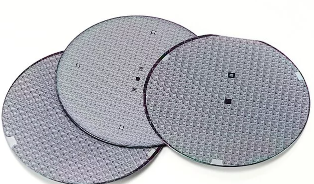
Achieving the correct wafer thickness before assembly is critical in semiconductor manufacturing. Wafer back grinding (or wafer thinning) is a semiconductor manufacturing process designed to control the wafer thickness, which is essential to produce ultra-thin wafers used to create stacked and high-density packaging in compact electronic devices.

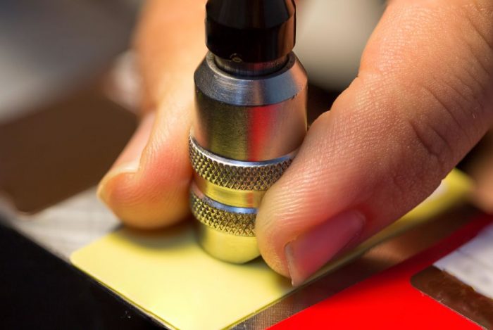
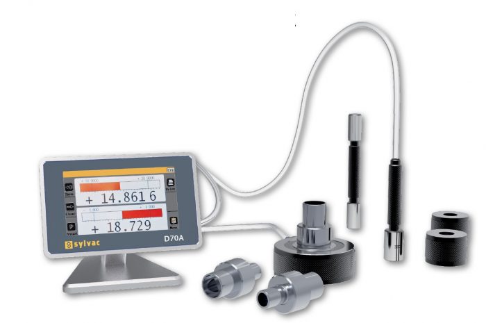
Wafer thinning is always a critical process. The chips are already present on the wafer and any failure in the process affects the production yield and costs. Tight in-line control on the thinning in-process operation is possible using contact gauges or non-contact sensors, even in the presence of DI water. Our offering of sensors helps in obtaining a repetitive final thickness of the wafer during the time.

The thinning operation is usually performed in two steps: rough grinding and finish grinding. The first one is used to remove most of the silicon amount during the finish operation just a small amount is removed till the desired final thickness that is normally less than 100µm. Willrich Precision offers  a contact gage that can easily control the rough thinning phase and because of its robust design, can survive in DI water without adding unwanted contaminants that could be dangerous to the wafer.

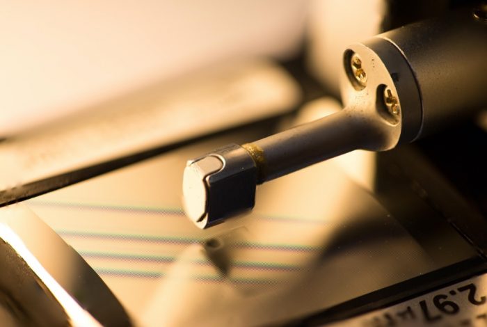
The same is for our offering of non-contact gauges that are particularly useful in the finish phase where particular care has to be taken in order not to damage the wafer.

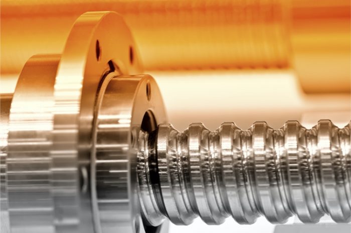
Willrich Precision is able to supply different gaging solutions to check the thickness of silicon, sapphire, SiC or any other material wafer used in the semiconductor industry. We have gaging systems that control the wire bonding dimension during the drawing process too. Are also available a collection of sensors that are installed on machine tools to measure the physical quantities that affect and govern the machining processes.

Grinding evenly

After sawing the wafers are thinned using mechanical processes such as grinding and lapping. During the grinding of a raw wafer or structured wafer certain quality parameters must be maintained. For raw wafers, for example, the TTV value indicates uniform removal during grinding. The TTV value is statistical value based on a metrological wafer thickness measurement indicating the absolute thickness variation of the entire wafer. The point here is to determine the maximum difference between the thickest and thinnest point, the so-called Total Thickness Variation (TTV).

In the thin wafer polishing process, a polishing pad applies pressure to make contact with the wafer surface and polishes it. A polishing paste (slurry) containing chemically effective substances and abrasive materials are used. The removal on the wafer surface occurs by friction. In a dry-polish process, the chemical and abrasive material is bound in a pad. In this process, a lower contact pressure is sufficient. Optical measuring systems are used for the monitoring of the polishing process, because the determination of the roughness allows conclusions to be made about the surface quality.

Smooth polishing

In the thin wafer polishing process, a polishing pad applies pressure to make contact with the wafer surface and polishes it. A polishing paste (slurry) containing chemically effective substances and abrasive materials are used. The removal on the wafer surface occurs by friction. In a dry-polish process, the chemical and abrasive material is bound in a pad. In this process, a lower contact pressure is sufficient. Optical measuring systems are used for the monitoring of the polishing process, because the determination of the roughness allows conclusions to be made about the surface quality.

It has to be flat: The perfect wafer

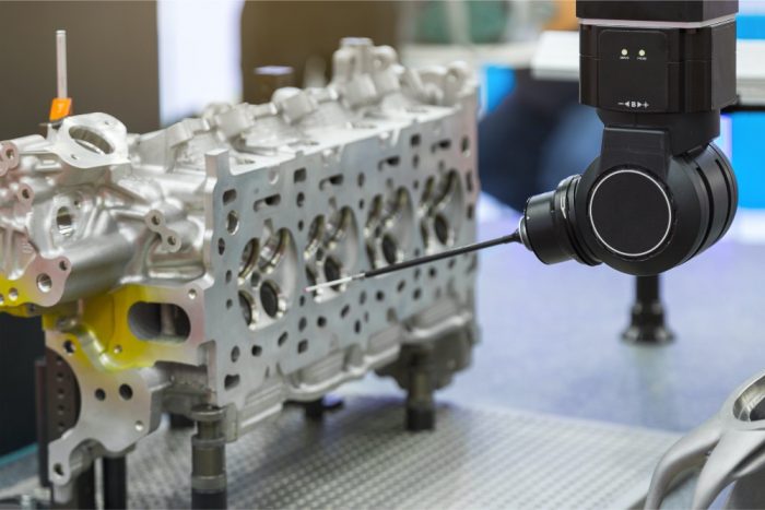
The surface finish of the wafer is characterized by its flatness. The flatter the surface, the more perfect the wafer is. Differences in height may lead to contacting problems during subsequent stacking to a 3D IC wafer package.

In addition, the wafers must be ground to an exact thickness and the doping introduced into the substrate should not be removed too far. The wafer edge can also be checked at random with a 2D profile measurement. From this, the wafer manufacturer can determine the wear of the grinding tools and optimize the process parameters. Waste at the edge of the wafer also plays an important role. The more efficiently this is done, the more microchips can be produced on the wafer later and the so-called fill factor increases. Processed wafers that are equipped with bump structures or solder balls, for example, can be measured in terms of height, width and coplanarity.

Willrich Precision offers many different gaging solutions to achieve wafer flatness measurement and wafer thickness measurement

Things You Need To Know Before Choosing An Ultrasonic Thickness Gage

ultrasonic thickness gage

Before you choose your ultrasonic thickness gage, you have to consider a number of factors. Some of the obvious factors include your budget constraints and also the reason you are buying it for. However, if this is your first-time purchasing equipment like this, then you might not be familiar with some of the other factors which might not be as obvious. It is important to note that these factors might be equally worth considering when choosing an ultrasonic thickness gage from such a competitive market. Furthermore, there are many factors that you need to consider when talking about the application of the instrument.

Before choosing the one that you want to get, you should find out exactly what you can and cannot do. Here at Willrich Precision Instrument, we provide a wide range of metrological products for any of your industrial needs.

Ultrasonic Thickness Gages Explained

Ultrasonic testing to measure thickness is becoming a very popular method. The main reason for using this device is that it can test the thickness of a wall without any form of destruction. It is usually used for the detection of thinning walls as a result of corrosion or as a method used for quality assurance. It can also be used for measuring boilers, aircraft materials, and even pipes.

The market for ultrasonic thickness gages is extremely competitive and there are many different manufacturers. The entry-level handheld units might cost as low as a few hundred dollars and can reach up to thousands of dollars. Usually, the software used for such products are very similar, but manufacturers can alter the internal software to cater to more specific needs. Many companies around the world offer the option to upgrade their products. As a result, a simple thickness gage can be upgraded to a device with datalogging capabilities and live waveform features.

The Material of Your Ultrasonic Thickness Gage

It is essential that you also list out the materials and the range of thickness for each material that you might want to test. Additionally, you should note down the accuracy that you want to achieve, the temperature when you are taking the readings, and the finish of the materials. In the case where a fluid can be applied to it, the fluid is most likely soluble in water and suitable for use with high frequency sound waves.

Considering the Weight and Size

When contemplating which model to purchase, some factors that you should consider include the weight and size of the ultrasonic thickness gage. Firstly, you must check if you have sufficient storage space for the size that you are looking for. Some ultrasonic thickness gages are compact and portable. They can even fit inside your pocket because they utilize AA size alkaline batteries that everyone knows are extremely portable.

On the other end of the spectrum, there are much larger gages because of the battery that they use. For example, if you need long-lasting battery life that uses latest lithium ion technology, then chances are your unit will be much larger. Additionally, you should consider how easy it is to service the unit that you want to buy, bearing in mind the place of manufacture and their reputation in this industry.

The Four Main Types Of Coordinate Measuring Machines

coordinate measuring machines

If you have no prior knowledge about coordinate measuring machines, then this article is for you. In the current market, there are four main types of coordinate measuring machines. These include the bridge, cantilever, gantry and horizontal arm coordinate measuring machines. They all have their own advantages depending on the components that you want to measure. Here at Willrich Precision Instrument, we understand that buying a coordinate measuring machine might not be as simple as you think. There are many types and factors to consider. However, we provide a wide variety of precision instruments for any of your industrial needs.

Bridge Coordinate Measuring Machines

Bridge machines have become increasingly popular over the years. This type of measuring machine allows for probe movement along 3 different axes, X,Y and Z. The unique thing about this machine is that each axis contains a sensor that can judge the position of the probe on any particular axis. It is capable of doing this with micro-meter precision. The bridge machine produces something called a “point cloud” which is done by sampling the three sensors and measuring a particular point on the object.

They have a very simple structure and is easy to use. Bridge machines are also cheap to manufacture and can withstand the test of time by maintaining accuracy consistently. Usually, bridge machines are fixed on a precision granite plate and have two legs to support the carriage. It is interesting to note that a typical bridge machine is only driven on a single side while the other sides are allowed to float freely. Close to 95% of them utilize air bearings so that there is greater ease of movement.

Cantilever Coordinate Measuring Machines

The cantilever coordinate measuring machines are typically used to measure smaller parts. In comparison to the bridge machines, they grant access to the user on three different sides. They also only allow for probe movement on X and Y, creating limitations on the size of the X beam. The rigidity of the machine makes it only suitable for measuring smaller parts. This type of machine will work well in a shop-floor setting because it has automatic loading and unloading capabilities as well.

Gantry Coordinate Measuring Machines

This type of machine is made specifically for measuring parts that are larger in size and heavy in weight but require the precision of a bridge coordinate measuring machine. Typically, gantry machines work best mounted to the floor. Thus, it is important that you provide it with a solid foundation. The smaller machines utilize four upright columns that support the Y-axis beams. On the other hand, larger gantry machines have 6 to 8 columns in relation to the length of the Y-axis.

Horizontal Coordinate Measuring Machines

The horizontal arm machine was first manufactured in Germany and were originally used as scribing tools. The first models were operated manually and were much harder to use as compared to today. The horizontal arm machine is different from the other three types in the sense that is has 2 axes mounted on a saddle that moves up and down the horizontal axis.

Understanding The Role Of Force Measurement In Linear Drives

force measurement

Force is defined as an interaction that has the ability to change the direction of an object. This, however, is only on the condition that the process is unopposed. Force is capable of making any object with mass to alter its velocity and this also includes objects that were initially at rest. Force takes many forms but is inherently either pull or push action applied onto an object. Force tends to have magnitude (how much of the force is being applied on the object) and it also has direction. For this reason, force always has a vector unit. When looking at force, there are certain concepts that one needs to understand.

Key Terms to Understand

There are a number of concepts that are common when talking about force. Thrust refers to the process of increasing the velocity of an object. There is also drag which counters the effect of thrust and decreases the velocity of an object. Another common term that is used when discussing force is known as torque which affects the rotational speed of the object in question. Another term that is common in this field is static. This refers to the description of objects that are at rest. In such cases, there is zero force acting on the object. Static can also happen when there are two opposing forces of equal magnitude acting on the object.

How is Force Measured?

There are various technologies that are used to measure force. These include Thin-film technology where a sputter process is utilized to achieve an atomic bond between the measuring bridge and the measuring cell body. This process is very ideal for measuring force in highly automated processes. Another common approach is to use a strain gauge where a resistance meander is attached to a strip of foil and this is then attached to the point where force is being applied.

Linear Drives

Linear drives are systems that cause translational movement. Because machine elements accelerate in a straight line, it’s logical to have force measurement in those drives as transformational change is taking place. Drive elements have traditionally been driven by hydraulics or are pneumatically powered. This is increasingly changing, and these kinds of drives are being replaced by electric motors, mechanical thrust units or a combination of both. Although these modern systems work through modular systems, they can be adapted to specifically match the needs of the user. The modern systems also have a greater degree of versatility. The only drawback of these systems is that you can no longer measure the pressure of the system.

Advantages of Force Measurements

Force measurement can be done with any linear drive. When you are looking to make precise force measurements, you can place the force transducer anywhere within the system. This will not affect the accuracy of the measurements that you take. Whether you place the force transducer on the actuator, the motor or the precise point where the force is being applied, you are still likely to get the right results.

Understanding Ra Values for Product Development

Ra values

Surface roughness is also known as Ra, but not many people understand what Ra values implies, how it is measured, and why it is critical to product design. Here is what you need to know about Ra values.

Understanding Ra Values

If you take a sample of a part and measure the high and low points of its length, Ra is the mean or average height that lies above or below the line of reference. The higher the Ra number, the rougher a surface is. If Ra is 0, the graph will show a horizontal line, which means the surface is flat. This is impossible.

Other measurement systems operate on the same principle but are not precisely similar. This can cause errors and confusion, so it is essential to know which method you are referring to and to ensure it is identical to that of your part manufacturer. Always ask if you are not sure as conversion charts are available for system-to-system translation if required.

How the Ra Value Concerns You

The Rvalue is the industry standard for giving instructions to a manufacturer on what the roughness level should and should not be for you. This is used for tooling, machined parts and prototypes. It also affects the part’s appearance, functionality as well as its performance.

Ra shows the average mean deviation or the highest high or low, calculated over the sample’s length. There are many ways to achieve the same mean by using various manufacturing processes. All of which will leave a distinctive pattern on the surface. Manufacturers utilize gages to measure and make comparisons on how different machining methods produce differing types of textures.

The patterns on the gauge surfaces differ in the groove spacing, also known as waves. It is one of the factors that determine surface texture. The waves found on the left are of a low frequency, and the frequency increases from left to right. The R, average height, may be similar but the appearance is not.

How Surface Texture is Measured

Surface texture can be measured with different methods, depending on the part geometry, material type, and part feature. A common technique is to use a stylus or probe, also called a surfometer. It is slowly drawn over the part’s face or feature. Any deviation from a reference line is recorded as a gap to be interpreted later.

The Ra value is calculated with ease via such a reading. It may be more desirable to look at the surface area from a broader view to check for more defects on the surface. This can be done via optical photometry.

One primary utilization of optical photometry to identify asperities. These may be scratches, contaminants in the raw material or voids. Mathematically obtained models tend to consider these irregularities as non-important, but for essential applications in defense, scientific and aerospace instruments, an anomaly would be disastrous.

It takes a combination of both machine and human intelligence for the right decision on surface texture to be made.

Do You Need Coordinate Measuring Machines Or Vision Systems?

coordinate measuring machines

Oftentimes, you get confused about which measurement system can best be applied in an in-house lab. The answer is usually either a Vision System or a Coordinate Measuring Machine (CMM). The CMM style probing has grown in popularity in use for vision systems. This makes choosing which system to apply in your business less straightforward. The following post aims to explain some important factors that need to be considered in order to make your decision of which measuring equipment to use simpler. Some of the important factors to consider when deciding on coordinate measuring machines or vision systems include:

Size 

Always have the size of your smallest feature in mind when choosing an inspection system. Vision systems are more accurate when dealing with smaller features of about 3-5mm. As for larger features, you need not worry about them since both coordinate measuring machines and Vision Systems can be used to handle them.

Variety 

One of the key considerations to keep in mind when choosing a measuring system is the nature of the characteristics to be measured. You can equip your Vision systems with full probing, to make it a CMM for rapid coordinate metrology. By integrating the CMM with the Vision systems, a high speed, highly automated, 3D coordinate acquisition system can be developed. Its potential applications can be used in a broad spectrum of manufacturing problems with a big impact on inspection and metrology. 

Speed 

Vision Systems are less dependent on probe approach speeds and moving probes. This gives them the potential to move faster, 5-10 times faster than other measurement systems. 

Number 

For the longest time, Vision systems have been used in 2D measurements. The ability to use CMM and vision probing on the same machine as well as interchangeably makes Vision systems the go-to measurement system in most 2½-Dand 3D applications. Vision systems and the part 2D in nature, are the preferred choice of measurement system in the event that the main datums are visible on one view of your print. 

From the above, it is safe to say that choosing which measurement system to use is not as black and white as some would think. A lot of key factors need to be put into consideration when deciding on which system to go for. 

At Willrich Precision Instrument, our staff is ready to guide you in determining which system best suits your needs. We are ISO certified and have been in business for over 40 years, offering solutions pertaining to gaging, inspection and metrology. We work diligently to maintain customer satisfaction by providing expert assistance through our knowledgeable staff. 

If you would like to discover more about our products and the services we offer, feel free to contact us today. 

What You Need To Know About Thread Inspection

thread inspection

Thread inspection is described as a ridge of uniform sections in the form of a helix on the external or internal cylinder surface. External threads are found on studs, screws, or bolts, while internal threads are located on tapped holes and nuts.

A large number of machine parts that are fastened to each other are attached via threading. Accurately produced threads are critical for each thread to bear the load evenly. If the male or female threads have a manufacturing flaw, the load distribution will be uneven, meaning some threads will bear more weight than they should. This can be quite disastrous, thus the importance of thread inspection.

Thread Inspection Basics

If you join two parts via threading, the two types of threads are male and female, with the male screwing into the female. As mentioned above, the two types of threads are internal and external. In a nut and bolt example, the bolt is the male and the nut is the female. The nut has threads on the inside, meaning it is an internal thread, and the bolt has threads on the outside, which makes it an external thread.

For the nut and bolt to fit each other, they have to be machined to the same size. The external thread diameter must match the internal thread’s smallest diameter, the pitch of the thread must match, the thread quantity per given length must match, and much more. 

The geometrical measurements needed to inspect a threaded component would be very labor and time-intensive and thus impractical. The solution to this is thread gaging.

Thread Gaging

Thread gaging is the process of inspecting threads, and there are two types of thread gauging:

  • Thread Plugs: Thread pugs are plugs that have external threading, and they are used to measure internally threaded parts such as nuts.
  • Thread Rings: Thread rings are the opposite of thread plugs. They are rings with internal threads and are used for measuring externally threaded parts such as bolts.

Thread plugs and rings are made from old gage steel, which is exceptionally resistant to wear.

Basics of Thread Gaging 

All threads are considered as attribute gages, which mean they do not give any feedback on the exact dimensions. This differs from the measurements you would get from a caliper, which provides you with the precise measurements of whatever you are measuring. 

Thread gages have what we call a Go/No-Go measurement. A threaded plug best explains an example of this measurement. For inspection of the internal thread, the ends of the plug are inserted into the threaded part. The plug’s Go-end should thread in, while the No-Go end should not. If the Go/No-Go test works, the component passes the inspection. If the Go-end part does not fit, then the threaded portion is too small, and vice versa. If the No-Go end fits, then the threaded part is too large.

A thread ring works based on the reversed version of a similar principle. The rings come in a set, and the Go ring is machined to a size smaller than the nominal while the No-Go ring is manufactured to be a little bigger than the nominal. In short, the Go ring is supposed to thread into the machined part while the No-Go ring is not supposed to do so. The Go/No-Go method of measurement is swift and very accurate.

Understand The Three Rs Of Sensor-Based Mechanical Measurements

Sensor-Based Mechanical Measurements

When you are dealing with sensor-based mechanical measurements, there are three important Rs that you should be aware of. These are Resolution, Response, and Repeatability. Understanding how these apply to your sensor-based mechanical measurements will ensure consistent and accurate results from instruments designed to take sensor-based mechanical measurements.

Repeatability

This
refers to the measure of variability in the results of a sensor-based measuring
system. Repeatability applies for a number of trials of an identical object in
an unchanging environment. Typically, quality control engineers will run about
three to five trials in order to establish repeatability. In a machining
process, this parameter is usually established by taking the average of the
variations in outputs across the various trials that have been done. It is
often expressed as a percentage of total output although some production
processes express repeatability as an absolute term.

One
thing to note when working with this parameter is that the tests must be done
exactly the same way for it to be effective.

Resolution

This
is the second R and it measures the least variation in the input to a
sensor-based measuring system to produce a measurable change. This parameter is
affected by, among other things, the signal-to-noise ratio of the analog
output. This noise often masks changes in the system’s output and the machinist
should be aware of this variable. When expressing resolution, many quality
control systems express it as a percentage of the total output but some express
it in absolute terms.

Response

This
parameter looks at the sensor-based measuring system’s operation while under
rapidly changing conditions. This parameter is not just a sensor specification
but is a measuring system parameter. Response is characterized in several ways
such as bode plots and phase lags. The purpose of this parameter is to look at
how well a measuring system can hold up to changing inputs before the readings
become unstable.

It is important to note that all these three parameters are interconnected and affect each other. For example, repeatability can be affected if the resolution is inadequate and so on. Machine operators must always be aware of system-level interactions that affect the overall accuracy of these measurement units. The other thing to remember is that machining environments rarely offer the constant environment that these sensor specifications are designed for. There will likely be variations in temperature, humidity and much more. Being aware of all these factors allows a machine operator to correctly calculate and translate these readings. At Willrich Precision Instruments, we do more than just sell high-quality instruments. Over the last four decades that we have been in operation, we have built partnerships with our partners that are mutually beneficial. Our clients can count on us for that personal touch that our physical presence brings. That notwithstanding, we also have an online presence for speed and convenience. By being both online and having a ‘brick and mortar’ presence means that our clients can always get personalized service if they wish. They can also enjoy the speed and convenience of shopping online from our store.

Understanding The Use of Equator Gauging Systems In EV Production

Equator gauging systems EV production

Equator gauging systems are specifically
designed for the needs of production lines. They make it possible for
production engineers to perform high-speed measurements accurately and with
much more flexibility than standard gauges can allow. The systems can be
tailored to meet the specific needs of a particular production line complete
with accessory options for manual and automated production lines.

The system works by comparing a pre-set master with the parts that are being measured. Equator gauging systems are also able to compensate for thermal conditions in the shop floor, making readings far more accurate. The gauges also come re-zeroed which eliminates the need to configure them before they can be used. These properties have made these gauges popular in many industrial processes and more so the production of electric vehicles or EVs. Here is how these gauges are transforming the production of EVs.

Equator
Gauges in EV Production

Any
car production system requires the fast and accurate measurement of hundreds of
parts and pieces. The accuracy of this gaging process plays a role in the
safety and reliability of the cars that come out of that proves. This is where
the equator gauging system has really made a difference in the production
lines. These gauges have been so effective that thousands of them are in use in
EV production lines across the United States, Europe, and Asian markets. The
system has worked especially well with the MODUS programming software that allows
for customization of the gaging process to suit the needs of any production
line.

Complete
Control

Using the
equator gauging system, production engineers have complete control over the
production process. To make it more powerful, the gaging system is compatible
with the Intelligent Process Control (IPC) software that enables the automatic
monitoring and adjustment of all machining processes in a production line. By
making this process automatic, production speed is significantly improved while
variances from the set master are minimized considerably. This, in turn,
reduces wastage and significantly increases revenue.

Manual
Vs. Automated Gaging

Another
advantage of equator gauging systems is that they can be customized to work
with the same application demands of other gaging systems. As EV production
becomes more and more automated, the equator gauging system comes with the
ability to work in automated systems which include robotic machines and
conveyors. What this means is that the system can work with existing systems
but is also ready for the future of automotive production systems. The system
can also be customized to work in harsh environments. In such a case, the equator
gauging system is installed in an enclosure that protects the system. Parts can
then be loaded and removed without interfering with the system.

Willrich Precision Instruments is your seller of choice for a wide range of precision measuring instruments for the last forty-five years and we back all our products with excellent support and warranties.

Understanding the Use of Air Gaging in The Automotive Industry

Air-gages

Air gaging is the use of compressed air to measure small spaces and hard to reach areas. Air gaging works by forcing a stream of air through finely tuned nozzles. The air gage then measures various dimensions of the space based on the air backstream. Air gages have over the years become hugely popular due to their flexibility and ease of use. Air gages have been used in the automotive industry for many years. Here are some of the ways that these useful gages serve the automotive industry.

Measuring Connecting Rods

Connecting rods are rigid components of the engine that link a piston to a crankshaft. By doing this, the connecting rods help to transform reciprocating motion into rotating motion or vice versa. Connecting rods are found in many types of engines but the most popular use is in automobile engines. Connecting rods require a very high degree of precision for them to function adequately. If one of the connecting rods fails, it often results to complete engine failure.

Use of Air Gages

During the manufacturing process, air gages are used to measure the distances between the piston end of the connecting rods and the crank end bores. Care is taken to ensure that the diameter, flatness of the parting surface and many other elements of the connecting rods are standardized and are up to the required dimensions. This is because any error in these elements can cause the engine to perform at less than its optimal level.

Air jets are used because they are insensitive to the diametrical size as well as to rod movement. This way, any variability associated with operator technique is eliminated. Accurate measurements can be taken fast and easily. This is especially useful in a factory setting where these parts are typically produced in their thousands every day and quality control operators need to measure random samples fast and accurately.

Workbench Version

The bend and twist gage have a bench version. This particular gage is good for busy workshops with a high volume of inspections. The device has a bend and twist fixture and also has an air to electric converter. The design of the gage is configured for easy and fast loading of workpieces. The data is also captured on the user interface and can easily be transferred on to a computer or another type of platform for analysis and storage

No Wear and Tear

One other reason why air gage is popular in the automotive industry is the fact that they are not susceptible to wear and tear. This is unlike contact gages such as calipers which come into contact with the part being measures. Air gages also clean the surface that is being worked on, meaning that dust and other elements do not affect the integrity of the readings from the air gage.

In conclusion, air gages are a bedrock of the automotive industry. As we have seen, they offer a flexible and fast way to measure samples.

There’s More Than One Approach Toward Air Gaging

air gaging

Air gaging was first developed as a technique to measure automotive parts. The gage worked by sending a stream of air into a bore and comparing the resulting airflow to a fixed amount of airflow. Air gaging has changed over the years, but the principle remains the same. Modern air gages measure the backpressure while the old gages were known as flow gages. Modern approaches to air gaging take different forms. Here are some of the commonly used methods.

Back Pressure Bleed System

This is a versatile form of air gaging where the air gage has an air regulator to control incoming air pressure. The gage also has a second restriction where the operator can adjust for various air gage tooling and readouts. This is done by adjusting the air pressure to match the kind of tooling being applied at the moment. This system also has its magnification controlled by the restriction between the regulator and the air gage. The second restriction serves to calibrate the tool and helps to establish the tolerance range of the tool.

The advantage of the bleed system is that it allows this air gage to operate at higher pressures than most other systems. These air gages also last much longer than most other systems because the nozzles are situated further away from the measuring surface thus reduced wear and tear.

Back Pressure System

This is simply a variation of the bleed system without the second restriction. This lack of a second restriction severely limits the applications of this air gage. For accurate readings, this air gage requires tooling and amplifies with restricted ranges. For this reason, many manufacturing processes do not use this kind of air gage.

Differential System

This type of air gaging is also known as a balanced system where the air is split into two and moves through these two channels. One end has a zero valve which is used to balance the pressure on the second airflow which terminates at the air plug.  A differential pressure meter measures the difference between these two legs and the gage is usually set to zero. One of the drawbacks to this kind of tooling is that the single-master system has a fixed magnification. This means that any bad or worn-out tooling must be taken back to the manufacturer as this would have an adverse effect on the readings being taken by the tool. This kind of air gaging also has each amplifies accommodating only one full-scale value. For that reason, different tolerances require several amplifiers.

Flow System

As discussed, these were among the original air gage and worked by measuring the airflow variation in a tube which holds a float. Flow systems are fairly accurate as they work with a two-master system and the range of magnification can be adjusted by changing flow tubes. Flow gages require a larger amount of air and nozzle sizes generally vary from brand to brand.

Air Gaging Is An Accurate Way To Measure Physical Qualities

Air Gaging

Are you new to the term: air gaging? Firstly, you will need to know how gage is defined. It is basically a tool and service used to measure a physical quality. This means that the gage can be used in any scheme of quantity production interchangeably. In addition to measuring the contents of something, these gages also come with visual displays that output certain facts such as time. Secondly, we look at air gaging. This concept relies on a law of physics that states pressure and flow react inversely to each other and/or are directly proportional to the clearance. In other words, air pressure increases, and air flow decreases when the clearance decreases. Air flow increases and air pressure decreases when the clearance increases.

The
Birth of Air Gaging

Air
gages were first used in quality assurance programs in the late 1910s. After flow
meter instruments with operating pressures of 10 PSIG (pounds per square inch
gauge) were developed in the late 1930s, practical dimensional air gages
started to surface. During the 1940s, however, there was an increased
demand for tighter tolerances
.

By
combining the power of computers and microprocessors, electronic pressure
sensors were instruments that drove the air gage display into the 21st century.
Compared to mechanical gages, air gages were significantly simpler and more
affordable to engineer. Oftentimes, these types of gages do not require linkages
to transfer mechanical motion. These unique features allow for the contacts to
be spaced at virtually any angle and very closely.

Which
Physical Qualities can be Measured via Air Gaging?

Below
is a quick look at the common physical qualities that can be measured via air
gaging:

  • The definition of thicknesses
  • A liquid’s flow pressure
  • Diameters of materials
  • Spaces between gaps

What
makes all these possible? You see, gages are instruments used to compare or
measure a component, as well as for dimensional control applications. In
addition to displaying measurement units on a digital monitor, the needles and
pointers work together by moving along a calibrated scale. By employing the
instrument in the sense that it has a fixed dimension, one can use it to determine
whether the size of one or more components exceed or is less than the gage’s
size.

Why
does Air Gaging Matter Today?

Due to
the accuracy of air gages, they are increasingly used in a wide range of
physical quality measurement applications. They offer adequate reliability and magnification
to measure small tolerances. The gages can also measure fluctuations in flow
rates and pressure (thanks to compressed air). In today’s time, tolerances on
the shop floor have gotten tighter. Many operators heavily rely on air gaging
to quickly and easily perform routine checks.

Understanding
the Overall Service Lifespan of Air Gages

It
goes without saying that the true value of a gage is measured by its service
lifespan and accuracy. Oftentimes, air gages are also subject to regular and
rough use. If you want to get an air gage that lasts, you will have to pay
attention to the product’s workmanship and materials used to manufacture it.

Understanding The Importance Of Repeatability

Repeatability

Repeatability
and accuracy form an inseparable pair in the world of precision measurement.
Although both terms share the same level of importance, repeatability has a
huge influence over the precision of a measurement. Read on to learn more about
the concept of repeatability and its place in the field of metrology.

An
Introduction to Repeatability

Repeatability refers to the degree to which consecutive measurements are taken successively under the same conditions. In other words, the concept informs technicians how close a series of measurements of a workpiece were when they were taken in a row with the same operator, tool, and machine.

It is useful to note that test-retest reliability is another term for repeatability. It involves re-measuring or re-testing an area or item and expecting to get essentially the same output. If the same measurement is not achieved, it indicates that the device or tool is not reliable. In this case, the operator has encountered variability issues. Variability can be caused by various reasons:

  • Stability of the part that’s being measured
  • Room temperature
  • Operator’s skills and experience
  • The measurement tool has not been properly
    calibrated

To
summarize what repeatable measurements are again; it is when operators get the same
values every single time the measurement is taken.

How
Important is Repeatability in Precision Measurements?

If you
gave measurements some thought, it will become obvious that it is often part of
a bigger project. Whether you are checking the standards, irregularities, size,
or alignment of a part, that part typically ends up a piece of a bigger end-product
that is going to be manufactured. Whether you are adjusting, cutting,
assembling, or machining a part, it will also be incorporated into that BIGGER
end-product.

While
measurements may seem like a small step in the creation of a final product,
machine, or device, the eventual manufactured piece will not be reliable
(contains irregularities) if previous measurements are not consistently the
same. That’s why operators and manufacturers need to achieve repeatability in
their measurements to guarantee quality in their products.

Repeatability
is a Stamp of Consistency

Oftentimes,
metrologists rely heavily on consistency for precision. That’s why they conduct
tests to guarantee, maintain, and check the repeatability of their
measurements. Below is how a typical test looks like:

  • One part, environment, device, or person
    becomes the subject.
  • The measurement device or tool is calibrated before commencing the test.
  • The operator defines a set of constant
    factors, e.g. the amount of data to be collected, environmental conditions,
    method of measurement, the operator, the test date, and test equipment.
  • Operator collects as much data as possible.
  • Operator assesses the repeatability of the
    measurement process by analyzing an array of descriptive statistics.

With
that in mind, it is highly recommended that measurement facilities conduct repeatability
tests on a regular basis.

Combine
Repeatability with Accuracy for Truly Precise Measurements

Although
repeatability is highly important for precise measurements (in its own right),
one must remember to pair it with accuracy to achieve an ultimately precise
measurement.

Conducting
repeatability tests need not be difficult at all as one can consider consulting
with metrology experts, such as Willrich Precision. Whether you specialize in the
medical or aerospace industry, we have got your back.

Why Should You Measure Orthopedic Devices With Air Gages?

Orthopedic Devices

Medical
implants need to be made from high quality orthopedic components so that they
can be used and kept by patients for as long as possible. This reduces or even
eliminates the need for additional surgical and non-surgical procedures down
the road. A good way to ensure the level of quality required is for orthopedic
device manufacturers to measure with high-precision air gages during the
product’s development and production phases.

Orthopedic
Device Manufacturing Challenges

Machining
and cutting are some of the individual manufacturing steps that must be consistently
stable in order to achieve precise orthopedic components that meet the necessary
high-quality standards. Oftentimes, as parts move through the manufacturing
process from raw materials to final products; geometric characteristics, surface
finish, and dimensional tolerance become increasingly critical.

Tight
tolerance is a dimensional characteristic that is often measured at the end of
the orthopedic device manufacturing process. It focuses on the tolerance on the
tapers that are used to match the components together. For example, most knee
and hip implants utilize tapers to enable optimal alignment and to secure (or
lock) the parts into position. During these processes, the control of both size
and taper will determine the performance of the orthopedic implants over their
service lifespan.

Air
Gaging: The Preferred Method

From
having the proper resolution to measure tolerances to having the right design
characteristics to fix parts together, today’s gages have to be robust when it
comes to manufacturing orthopedic implants. For many manufacturers, air gages
have become the inspection tool of choice for controlling such critical
parameters. Air gaging has proven itself to be an extremely precise measurement
method that provides very high resolution. It is now often used in applications
(e.g., precision medical tapers) where the tolerance tightness is less than
±0.001 in.

That’s not all as air gages are particularly well suited for checking dimensional relationships. They are easy to use, produce results quickly, and can last for years, even under the toughest shop conditions. One of the reasons why air gages are so useful for measuring orthopedic tapers is that they feature air jets, which are small orifices that emit air, and can be used to measure parts at the point of manufacture.

Common
Air Taper Gage Variations

Below
is a quick look at the different types of air taper gages that are used in
modern applications:

  • Jam-fit style air tool: Considered the most common type of air gage taper tooling. It
    features two pairs of jets and is designed to create a jam fit between the tool
    and the part (on opposing air circuits). This tooling does not measure part
    diameters but showcases the two points’ diametrical differences on a particular
    workpiece.
  • Clearance style air tool: Also known as a shoulder style air
    tool
    , this gage is used when an air taper ring
    cavity needs to be sized to accept the entire taper part. In addition, the air
    gage can be used to inspect for barrel and bell-mouth shapes, as well as
    measure diameters at known heights.
  • Simultaneous fit air tool: The third gage is a cross between the previous gages; it is essentially
    a jam-fit air gage that takes references from the face of the datum surface
    with the aid of an indicator. It is often used to indicate how far an air tool
    goes into the part that’s being measured.

How Does Air Gaging Fit Into Automated And High Production Manufacturing Environments?

air gaging

One of the biggest manufacturing industry trends today is the automation of inspection processes with the use of robotics. This trend is also expected to last for some time due to the decreasing costs of industrial robots, continuous innovation, and soon-to-have ability to inspect 100 percent of the critical dimensions of any workpiece.

Air gaging is also expected to continue evolving and remaining a relevant form of metrology in the modern, automated world. Some individuals might ask, “How would air gaging fit into automated and high production manufacturing environments?” “Isn’t it just used as a GO/ NO-GO gage to check for good and bad parts?” Well, not anymore.

Widely
Utilized in Automated Measuring Stations

Due to the changing demands of customer requirements in recent years, air gaging has evolved to the stage where it is now used in fully automated measuring stations. Today’s air gages can provide feedback to the machine tool for offsetting applications. Air gaging probes and rings, however, are some of the elements that have not changed much. They are mostly used to measure smaller diameters.

Control
units are now more advanced, and they are referred to as measuring computers,
columns, and comparators. These devices also contain features, such as RS232,
USB ports, Profibus, Ethernet, analog and digital inputs/outputs, among others.
These communication protocols allow for air gages to function in fully
automatic and semi-automatic measuring modes.

A
Typical Measurement Procedure

So,
how are these air gages set up and utilized in high production and automated
manufacturing environments? The gaging system is first calibrated, either
automatically or manually. For example, if the operator chooses the automated
way, a robot will load the MIN and MAX masters onto the gage. Once the masters
are loaded, the calibration process can be initiated with a programmable logic controller (PLC). Oftentimes,
calibration cycles are controlled either by using a manual trigger, a parts
counter, or a timer. In addition, calibrations are typically performed one time
per shift. Some technicians, however, may require it much more frequently.

Understanding
Measurement Cycles of Workpieces

Now that you get the gist of calibrations, the current focus will be on measurement cycles. For starters, the process is pretty similar where the robot loads the workpiece onto the gage before signaling the start of the measurement. The robots will then “listen” to the control unit to determine if the part is good or bad and sort the parts according to the information. The great thing about this is that the control unit will report offset values back to the machine so that adjustments can be made automatically, without human intervention!

One Setup for One Diameter Measurement

It is
important to note that this setup can only be utilized to check one diameter.
If one needs to measure several features, he or she must set up multiple
stations for the robot to “pick and place.” It is also a good idea to
integrate tracking serial numbers via a data matrix engraved on the part. This
allows for the measurement data of each individual part to be recalled or
stored at any time.

Plenty
of Room for Integration

Air
gages no longer just measure outside and inside diameters. They are now used to
measure flatness, runout, parallelism, taper, perpendicularity, and many more. It
goes without saying that the capability of air gages will continue to grow rapidly,
and quality professionals will want and need more room for integration in the
near future.