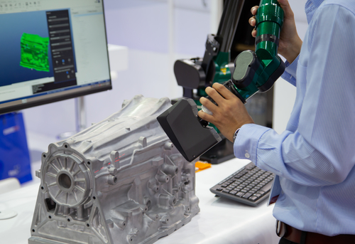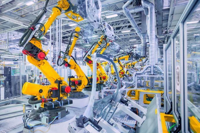
One of the biggest manufacturing industry trends today is the automation of inspection processes with the use of robotics. This trend is also expected to last for some time due to the decreasing costs of industrial robots, continuous innovation, and soon-to-have ability to inspect 100 percent of the critical dimensions of any workpiece.
Air gaging is also expected to continue evolving and remaining a relevant form of metrology in the modern, automated world. Some individuals might ask, “How would air gaging fit into automated and high production manufacturing environments?” “Isn’t it just used as a GO/ NO-GO gage to check for good and bad parts?” Well, not anymore.
Widely
Utilized in Automated Measuring Stations
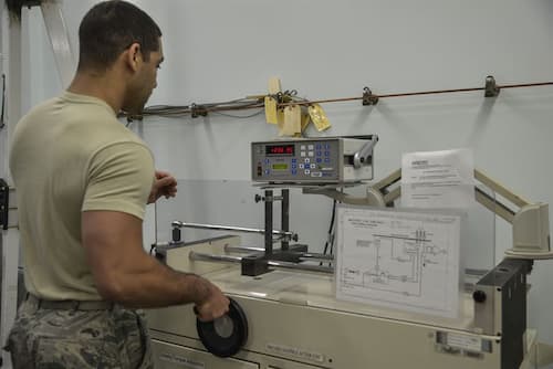
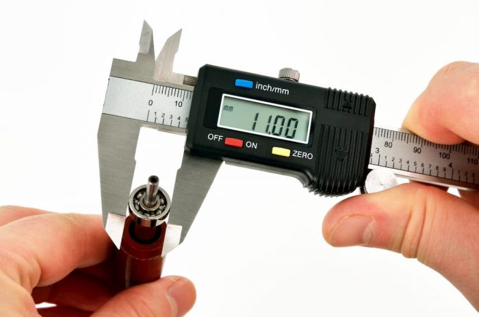
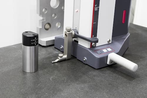
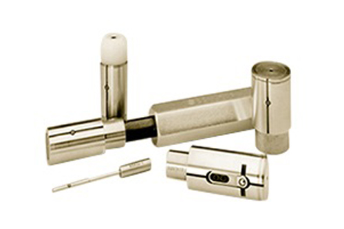
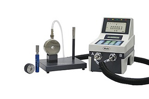
Due to the changing demands of customer requirements in recent years, air gaging has evolved to the stage where it is now used in fully automated measuring stations. Today’s air gages can provide feedback to the machine tool for offsetting applications. Air gaging probes and rings, however, are some of the elements that have not changed much. They are mostly used to measure smaller diameters.
Control
units are now more advanced, and they are referred to as measuring computers,
columns, and comparators. These devices also contain features, such as RS232,
USB ports, Profibus, Ethernet, analog and digital inputs/outputs, among others.
These communication protocols allow for air gages to function in fully
automatic and semi-automatic measuring modes.
A
Typical Measurement Procedure
So,
how are these air gages set up and utilized in high production and automated
manufacturing environments? The gaging system is first calibrated, either
automatically or manually. For example, if the operator chooses the automated
way, a robot will load the MIN and MAX masters onto the gage. Once the masters
are loaded, the calibration process can be initiated with a programmable logic controller (PLC). Oftentimes,
calibration cycles are controlled either by using a manual trigger, a parts
counter, or a timer. In addition, calibrations are typically performed one time
per shift. Some technicians, however, may require it much more frequently.
Understanding
Measurement Cycles of Workpieces
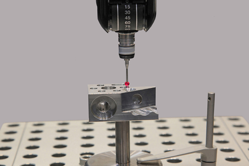
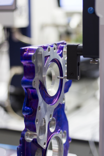
Now that you get the gist of calibrations, the current focus will be on measurement cycles. For starters, the process is pretty similar where the robot loads the workpiece onto the gage before signaling the start of the measurement. The robots will then “listen” to the control unit to determine if the part is good or bad and sort the parts according to the information. The great thing about this is that the control unit will report offset values back to the machine so that adjustments can be made automatically, without human intervention!
One Setup for One Diameter Measurement
It is
important to note that this setup can only be utilized to check one diameter.
If one needs to measure several features, he or she must set up multiple
stations for the robot to “pick and place.” It is also a good idea to
integrate tracking serial numbers via a data matrix engraved on the part. This
allows for the measurement data of each individual part to be recalled or
stored at any time.
Plenty
of Room for Integration
Air
gages no longer just measure outside and inside diameters. They are now used to
measure flatness, runout, parallelism, taper, perpendicularity, and many more. It
goes without saying that the capability of air gages will continue to grow rapidly,
and quality professionals will want and need more room for integration in the
near future.