Best Fixtures For Keyence IM-6225, IM-7020 & IM-7030

Keyence’s IM Series Instant Measurement systems are devices that help industries improve inspection and measurement efficiency. They include the IM-6225, IM-7020, and IM-7030 models. Advanced optics, high-resolution cameras, and powerful software work together in these systems. They capture and analyze images of parts, giving quick and precise measurements of dimensions. To get the most accurate measurements from these systems, you need to use the right fixtures to hold the parts in place during inspections. Let’s talk about the top fixtures for Keyence IM-6225, IM-7020, and IM-7030. We’ll explain their features and benefits in various industrial uses.

Universal Fixturing Solutions

Fixturing solutions work for many part sizes and shapes. They are an excellent fit for Keyence IM Series systems in different industries. These tools have parts that can be changed easily to fit different inspection requirements. They include adjustable components like clamps, bases, and supports.

Modular Fixturing Systems

Modular fixtures are widely used with Keyence IM Series devices. They are versatile, customizable, and a popular choice. The systems have a base plate and different parts like clamps, supports, and locators. You can put them together fast to make a custom fixture for any part you need. The design is modular, so you can quickly change it for different parts or inspections. It’s easy to adapt. Some modular fixturing systems that work with Keyence IM-6225, IM-7020, and IM-7030 are popular.

  • R&R Fixtures
  • Renishaw QuickLoad™ Corner (QLC)
  • Phillips Precision’s Inspection Arsenal®

Vacuum Fixturing Systems

Vacuum fixtures use suction to hold parts during inspection. They’re great for fragile or intricate parts that are hard to hold with typical clamps or supports. Vacuum systems have a base and vacuum cups. The cups can be changed to fit various shapes and sizes of parts. Vacuum fixturing systems compatible with Keyence IM-6225, IM-7020, and IM-7030 include:

  • VacuGrip™ Vacuum Fixturing Systems
  • Pierson Workholding’s SmartVac II™

Custom Fixturing Solutions

Custom fixturing solutions for Keyence IM-6225, IM-7020, and IM-7030 are important for precise and efficient inspections and measurements in multiple industrial uses. There are two ways to hold parts in place, 3D-printed fixtures, and machined fixtures. Each one has its advantages.

3D-Printed Fixtures

Additive manufacturing technology is used to create custom fixtures that match the size and shape of individual parts using 3D printing. This approach offers several advantages:

  • Rapid prototyping:  3D printing makes it fast to create fixtures, so manufacturers can test and improve their designs quickly.
  • Design flexibility: 3D-printed fixtures are easy to modify. Manufacturers can quickly change their designs to fit new part shapes or inspection needs.
  • Cost-effectiveness: 3D printing can lower the cost of making custom fixtures by removing the need for costly tooling.
  • Material versatility: 3D printing can use many different materials, like plastic and metal. This helps manufacturers choose the best material for their needs.

Machined Fixtures

Custom machined fixtures are made out of materials like aluminum or plastic. These fixtures offer several key benefits:

  • Precision: Machining can make precise fixtures that hold parts well for inspection.
  • Durability: Machined fixtures are stronger than 3D-printed ones and can be used for a long time in tough factories.
  • Customizability:  Machined fixtures are made better by adding clamps, supports or locators. This makes them more useful and adaptable to different parts and inspections.

Scalability: Machining is good for making things in large amounts. It’s easy to make more when you need to.

How Many Types Of Micrometers Are There?

Micrometers measure small dimensions with high accuracy and precision. They are used in industries like manufacturing, engineering, automotive, and aerospace. The measuring tool has two parts – a spindle and anvil. A screw mechanism adjusts them to measure object dimensions. There are different types of micrometers, each designed for specific purposes. To use them properly, it’s important to know their unique features and functions. This article gives an overview of micrometers and how they’re used in different industries.

  • Outside Micrometers

The most popular type of micrometer is the outside micrometer. It is used to measure the size of things outside, like the thickness of plates or rods. It can also measure the width of flats. The measurement tool has three parts: a U-shaped frame, an anvil, and a spindle. You can adjust these parts using a screw to fit around what you want to measure. The micrometer’s design determines how to read the measurement. It can be from a scale, dial, or digital display.

Micrometers are commonly used in metalworking, machining, and manufacturing to measure the size of products accurately, which is essential for maintaining quality and efficiency.

  • Inside Micrometers

Micrometer types for measuring internal dimensions are called inside micrometers. They can measure the diameter of holes, the width of slots, and the distance between two opposing surfaces. These devices have a rod or tube that includes a spindle and anvil. The screw mechanism adjusts them to fit the object being measured. The micrometer’s design will determine how the measurement is displayed. It may be shown on a graduated scale, dial, or digital display.

Inside Micrometersare often used in industries like machining, metalworking, and woodworking. They are necessary for maintaining product quality and process efficiency.

  • Depth Micrometers

Depth micrometers are used to measure the depth of holes, slots, or recesses in objects. The tool has three parts: a flat base, a tube with a spindle, and a screw to move the spindle. The micrometer’s design determines how you see the measurement – on a scale, dial, or screen.

Many industries like machining, metalworking, and manufacturing use depth micrometers. These devices ensure accurate depth measurements, which are crucial for maintaining product quality and process efficiency.

  • Tube Micrometers

Tube micrometers measure the thickness of tubes, pipes, and cylindrical objects. They’re made for this purpose. The tool has a U-shaped frame, an anvil, and a spindle. A screw mechanism is used to adjust them to the size of the object being measured. The anvil is round or cone-shaped to fit the tube or pipe.

Tube micrometers are often used in industries like automotive, aerospace, and manufacturing. They help measure wall thickness accurately, which is vital to maintain product quality and process efficiency.

  • Screw Thread Micrometers

Screw thread micrometers are designed to measure the pitch diameter of screw threads. The measurement tools have special anvils and spindles with matching thread shapes. A screw mechanism adjusts them to fit the threads being measured. The micrometer displays the measurement on a scale, dial, or digital display. How it shows the measurement depends on how it’s designed.

Screw thread micrometers are used in many industries like machining, metalworking, and manufacturing. They accurately measure threads to keep product quality and process efficiency.

  • Digital Micrometers

Digital micrometers, also called electronic micrometers, are a modern option to the older mechanical micrometers. The device has a screen that shows the measurement directly. You don’t need to do calculations manually and it reduces mistakes. Digital micrometers have extra features. You can switch between metric and imperial units. They can set zero at any position and send data to other devices, such as computers.

Industries, like electronics, medical, and precision engineering, use digital micrometers for precise measurements because they are becoming more popular. These tools measure the sizes of small parts, look at delicate components, and check quality.

Dial Vs. Digital Caliper What’s The Difference

Calipers are tools used in many industries to measure length, width, and depth accurately. They are essential in fields like manufacturing, engineering, and aerospace. Dial and digital calipers are very accurate, easy to use, and versatile. They are the most popular types of calipers available. We’ll compare the dial vs. digital caliper in this article. You’ll learn about their unique features, advantages, and disadvantages. This will help you choose the right measuring tool for your needs.

Dial Calipers

Dial calipers are tools that show measurement using a dial. The dial indicator has a needle that moves around a scale. You can read the measurement in metric or imperial units. The caliper’s jaws adjust to fit the object being measured. The needle shows the measurement on the dial.

           Advantages of Dial Calipers

  • Dial calipers tend to last longer than digital calipers. This is because they don’t rely on electronic parts that can easily get damaged by impacts, moisture, or temperature changes.
  • Dial calipers don’t need batteries or external power. They are great for users who want a measuring tool that’s always ready. They are reliable and low-maintenance.
  • Dial calipers are simple and easy to use. You can read the measurement directly on the dial. This makes them perfect for those who like straightforward tools.

Disadvantages of Dial Calipers

  • Dial calipers have lower resolution than digital ones. This can make precise measurements harder, especially for small or complex parts.
  • Dial calipers can have reading errors. This is because users have to read the dial’s measurement by themselves. It can lead to misinterpretation or parallax errors.

Digital Calipers

Electronic calipers, or digital calipers, display measurements on a screen, so you don’t need a dial or scale. The display shows the measurement in metric or imperial units. It can do other things, too, like switch the units, set zero at any place, and output data for computers or devices.

Advantages of Digital Calipers

  • Digital calipers have better resolution than dial calipers. This makes it easier to measure small and intricate parts with precision.
  • Digital calipers show measurements on a screen, so it’s easier to get accurate readings. That way, you don’t have to worry about making reading mistakes.
  • Digital calipers have more features to make measuring easier, like changing units, resetting the zero point and sending out data.

Disadvantages of Digital Calipers

  • Digital calipers need batteries or external power. This could be a problem if you need a measuring tool that’s always ready, or if you work where it’s hard to replace batteries.
  • Digital calipers may not be as durable as dial calipers due to their sensitivity to impacts, moisture, and temperature. This can cause reliability issues as they contain electronic components.

Factors to Consider When Choosing Between Dial and Digital Calipers

  • Accuracy and Resolution: Dial and digital calipers give precise measurements. But digital ones are easier to get exact measurements for small or complex parts due to their higher resolution. Your work may need high-resolution measurements. In that case, a digital caliper could be a better option.
  • Ease of Use and Reading: Digital calipers show the measurement directly on the screen. This makes it easy for users to get accurate readings and reduces the risk of errors. Dial calipers need users to read measurements from the dial. This can cause mistakes by making it hard to know where to read. If ease of reading is crucial for your work, a digital caliper may be the better option.
  • Durability: Dial calipers last longer than digital ones because they don’t have electronics that are easily affected by impacts, moisture, or changes in temperature. A dial caliper might work better if you work in tough places or need a sturdier measuring tool.
  • Additional Features: Digital calipers have extra features like unit conversion, zero-setting, and data output. These features can make it easier and faster to measure things. If you need more features, a digital caliper might be the best choice.

Best Fixtures For Keyence IM-6225, IM-7020 & IM-7030

Calipers are important measuring tools used in many industries, including manufacturing, engineering, automotive, and aerospace. They measure objects with high precision, both inside and out. There are many types of calipers, each with different features and benefits. It’s important to know what they do and where to use them. This article gives an overview of calipers. It explains their functions and uses in different industries.

Calipers Introduction

Calipers are tools used to measure the size of an object – its length, width, height, or diameter. These tools have two jaws that adjust to measure the size of an object accurately. Industries need precise measurements to make good products and work well. So they use calipers a lot. Technicians and engineers can ensure accurate measurements and high-quality standards by knowing different types of calipers and their functions.

  • Vernier Calipers

 Vernier calipers are common and have a main scale and a sliding vernier scale. The main scale measures in millimeters or inches. The vernier scale gives more precision for smaller measurements. The user places the jaws around or inside the object being measured. Then, they combine the main scale and vernier scale values to get the reading.

Vernier calipers are cheap and easy to use. They are favored in many industries. People use these to measure mechanical parts, inspect products and assure quality.

  • Dial Calipers

 Dial calipers look like vernier calipers but use a dial instead of a scale. The dial indicator shows the measurement directly. It’s easy to read and reduces errors. You can get dial calipers in metric or imperial units. They’re very accurate and precise.

Industries like aerospace, automotive, and manufacturing use dial calipers for precise measurements. They are often used to measure the size of mechanical parts, check finished products, and control quality.

  • Digital Calipers

 Digital calipers are a modern option to traditional vernier and dial calipers. They are also called electronic calipers. They have a digital display that shows the measurement directly. This removes the need for manual calculations and lowers the chance of errors. Digital calipers have added features. You can switch between metric and imperial units and zero-set them at any position. They also offer data output that lets you connect them to computers or other devices.

Industries like electronics, medical, and precision engineering use digital calipers for exact measurements. These calipers are becoming more popular. These tools measure small parts, inspect fragile components, and verify that quality standards are met.

  • Inside Calipers

Inside Calipersare made for measuring the inside of objects. For example, they can measure the size of holes, slots, or the space between two surfaces facing each other. They have bent or curved jaws which can adjust to fit inside the object being measured. This gives an accurate measurement of its internal size.

Many industries, like machining, metalworking, and woodworking, need to make precise measurements inside products. To ensure quality and efficiency, they use inside calipers.

  • Outside Calipers

Outside Calipers measure the outside of things like rods, flats, and plates. These devices have jaws that adjust to fit around the object you want to measure. This gives an accurate measurement of its size.

Industries like metalworking, woodworking, and manufacturing commonly use outside calipers. Accurate external measurements are crucial for maintaining product quality and process efficiency.

  • Divider Calipers

Divider calipers, also called compasses, mark distances and transfer measurements between objects. They have two sharp, pointed legs that can be moved to the desired distance. You can use them to draw lines or mark points on an object’s surface.

Divider calipers are often used in industries like woodworking, metalworking, and drafting. They help ensure accurate marking and layout, which are important for quality and efficiency.

6 Different Types Of Calipers & Their Functions               

Calipers are important measuring tools used in many industries, including manufacturing, engineering, automotive, and aerospace. They measure objects with high precision, both inside and out. There are many types of calipers, each with different features and benefits. It’s important to know what they do and where to use them. This article gives an overview of calipers. It explains their functions and uses in different industries.

Calipers Introduction

Calipers are tools used to measure the size of an object – its length, width, height, or diameter. These tools have two jaws that adjust to measure the size of an object accurately. Industries need precise measurements to make good products and work well. So they use calipers a lot. Technicians and engineers can ensure accurate measurements and high-quality standards by knowing different types of calipers and their functions.

  • Vernier Calipers

 Vernier calipers are common and have a main scale and a sliding vernier scale. The main scale measures in millimeters or inches. The vernier scale gives more precision for smaller measurements. The user places the jaws around or inside the object being measured. Then, they combine the main scale and vernier scale values to get the reading.

Vernier calipers are cheap and easy to use. They are favored in many industries. People use these to measure mechanical parts, inspect products and assure quality.

  • Dial Calipers

 Dial calipers look like vernier calipers but use a dial instead of a scale. The dial indicator shows the measurement directly. It’s easy to read and reduces errors. You can get dial calipers in metric or imperial units. They’re very accurate and precise.

Industries like aerospace, automotive, and manufacturing use dial calipers for precise measurements. They are often used to measure the size of mechanical parts, check finished products, and control quality.

  • Digital Calipers

 Digital calipers are a modern option to traditional vernier and dial calipers. They are also called electronic calipers. They have a digital display that shows the measurement directly. This removes the need for manual calculations and lowers the chance of errors. Digital calipers have added features. You can switch between metric and imperial units and zero-set them at any position. They also offer data output that lets you connect them to computers or other devices.

Industries like electronics, medical, and precision engineering use digital calipers for exact measurements. These calipers are becoming more popular. These tools measure small parts, inspect fragile components, and verify that quality standards are met.

  • Inside Calipers

Inside Calipersare made for measuring the inside of objects. For example, they can measure the size of holes, slots, or the space between two surfaces facing each other. They have bent or curved jaws which can adjust to fit inside the object being measured. This gives an accurate measurement of its internal size.

Many industries, like machining, metalworking, and woodworking, need to make precise measurements inside products. To ensure quality and efficiency, they use inside calipers.

  • Outside Calipers

Outside Calipers measure the outside of things like rods, flats, and plates. These devices have jaws that adjust to fit around the object you want to measure. This gives an accurate measurement of its size.

Industries like metalworking, woodworking, and manufacturing commonly use outside calipers. Accurate external measurements are crucial for maintaining product quality and process efficiency.

  • Divider Calipers

Divider calipers, also called compasses, mark distances and transfer measurements between objects. They have two sharp, pointed legs that can be moved to the desired distance. You can use them to draw lines or mark points on an object’s surface. Divider calipers are often used in industries like woodworking, metalworking, and drafting. They help ensure accurate marking and layout, which are important for quality and efficiency.

3 Common Methods For Setting A Dial Bore Gage

Dial bore gages are important tools in the automotive, aerospace, and manufacturing industries. They measure the size of cylindrical holes and can detect if they are not round. Before using the dial bore gage, it’s important to set it up correctly. This ensures that your measurements are precise and trustworthy. We’ll talk about how to set a dial bore gauge in this article. There are three common methods: using a micrometer, setting ring, or master bore. We’ll guide you in choosing the best method for your application.

Setting a Dial Bore Gage Using a Micrometer

Knowing how to set a dial bore gage accurately assures that measurements are correct. This helps maintain high standards of quality and efficiency in processes.

One of the most common methods for setting a dial bore gage is using an outside micrometer. To make measuring more accurate, use a micrometer as a reference standard and adjust the dial bore gage to match it. Here’s a step-by-step guide on how to set a dial bore gage using a micrometer:

  • Select the appropriate micrometer: Choose an outside micrometer that can measure the diameter of your intended bore.
  • Measure the bore diameter with the micrometer: To measure the diameter of the bore, use a micrometer. You can also get the target diameter from a blueprint or specification.
  • Adjust the dial bore gage: Adjust the micrometer’s spindle to extend the measuring head to the target diameter. Make sure the gage is parallel and aligned with the micrometer’s anvil and spindle.
  • Zero the dial indicator: To make sure the needle points to zero, keep the gage in touch with the micrometer and turn the dial indicator’s bezel.
  • Verify the setting: Double-check the gage’s setting by measuring the bore diameter again with the micrometer. Make small changes to the dial indicator to match the micrometer’s reading on the gage.

Setting a Dial Bore Gage Using a Setting Ring

Another common method for setting a dial bore gage is using a setting ring. Setting rings are cylindrical rings with a precise internal diameter. They act as a reference standard for adjusting the gage. Here’s a step-by-step guide on how to set a dial bore gage using a setting ring:

  • Select the appropriate setting ring: Select a setting ring that has an inner diameter close to the bore diameter you want to measure.
  • Insert the dial bore gage into the setting ring: Insert the measuring head of the gage carefully into the setting ring. Make sure the contact points are parallel and aligned with the ring’s inner surface.
  • Zero the dial indicator: To make sure the gage and setting ring stay in touch, turn the dial’s bezel until the needle shows zero.
  • Verify the setting: Double-check the gage’s setting by inserting the gage into the setting ring again. If needed, adjust the dial until the gage matches the internal diameter of the setting ring.

Setting a Dial Bore Gage Using a Master Bore

In some cases, a master bore can be used to set a dial bore gage. A master bore is a precisely machined cylindrical bore with a known diameter. It is used to set the measuring gauge accurately. Here’s a step-by-step guide on how to set a dial bore gage using a master bore:

  • Select the appropriate master bore: Select a master gauge that has a similar diameter to the bore you wish to measure.
  • Insert the dial bore gage into the master bore: Insert the measuring head of the gage into the master bore carefully. Make sure the contact points are aligned with the internal surface of the bore.
  • Zero the dial indicator: To make sure the gage and the master bore stay connected, turn the dial indicator until the needle points to zero.
  • Verify the setting: Double-check the gage’s setting by inserting the gage into the master bore again. Make small changes to the dial gauge if needed until it shows the same diameter as the master bore.

Embracing the Future: Dial vs. Digital Indicators and the Rise of Precision Instrumentation

In the early 1980s, the introduction of digital electronic indicators caused quite a stir in the industry. It was believed they would eventually overshadow mechanical dial indicators due to their enhanced resolution, accuracy, and utility in systems of statistical process control and data collection. Yet, mechanical indicators managed to hold their ground, largely due to certain advantages they possessed and the continued preference of many users.

Today, the digital versus dial debate is no longer about which is superior, but more about which is suitable for specific applications. The selection between the two relies heavily on the application in question and user preference. Nonetheless, digital indicators are emerging as the preferred choice for an increasing number of applications.

The Technological Advantage: Digital Indicators in Process Control

The primary advantage of digital indicators lies in their use for data collection in process control. With digital indicators, operators can output measurements directly, eliminating operator errors in reading or recording. This process has become even more streamlined in recent years with the introduction of wireless technology, which allows greater portability of gages. The only manual step is positioning the workpiece and pressing a button, the rest is taken care of by the digital indicator.

Conversely, dial indicators involve a more complicated, error-prone process where the operator must interpret the pointer’s position, record it manually, and then enter the data into a computer. As a result, digital indicators are the most logical choice when data needs to be entered into a computer system.

Affordability and Utility: The Cost-Benefit Analysis

Historically, the cost of digital indicators was considerably higher than that of dial indicators. However, this has changed in recent times, and basic digital indicators are now competitively priced alongside high-quality dial indicators. Moreover, digital indicators often come with additional standard features such as reversal of measuring direction, auto-zeroing, data output, in/mm switchable reporting, and actual values. This provides exceptional value in what used to be a premium product.

The Cognitive Appeal: Dial Indicators’ Unique Strengths

Despite the cost advantage being wiped out, there is still something intriguing about mechanical dial indicators. The human brain, like an analog device, can often glean more information quickly from an analog readout. Dial indicators also provide more intuitive information than digital ones. However, modern digital indicators have overcome some of these cognitive disadvantages by incorporating analog-like displays, providing an indication of direction, and showing how far over or under the part tolerance the item being inspected is.

The Digital Ascendancy: Today’s Digital Indicators

Many of today’s digital indicators are becoming increasingly powerful and feature-rich, rivaling bench amplifiers in performance. With features such as dynamic measurements, multiple factors, unilateral tolerances, different output formats, and micro-inch resolutions, these advanced digital indicators offer exceptional value, usually at a fraction of the price of a bench amplifier and probe.

Additionally, digital indicators eliminate certain common issues associated with dial indicators, such as overlooking when the pointer makes a full revolution or two. By displaying the actual part size, they eliminate the problem of returning to “0” or reading deviations.

Charting the Future with Digital Indicators

Digital indicators have proven to be highly reliable in the shop floor environment and are widely accepted by operators, thereby, gaining dominance in more applications. With only a single moving part, digital indicators require less frequent cleaning than their mechanical counterparts and now feature clear IP ratings that define their usable environments. Although dial indicators can last virtually forever and do not need batteries, finding professionals who can repair them is becoming increasingly challenging.

At Willrich Precision Instrument, we offer a comprehensive range of metrology products, from the most sophisticated metrology products to basic measuring tools, including both dial and digital indicators. Experience the ease and accuracy of digital indicators with us.

MEASUREMENT

Foreword

This book stems from many years of discussion and tireless introduction of measurement and inspection technology to those in industry responsible for the control of product quality. It became clear that there are few outside of the quality profession who understand and appreciate the measurement process, its implications and its techniques. I hope that through the use of this primer there can be a better understanding of what it takes to “take a measurement”.

MEASUREMENT

By:

Richard G. Chitos

What is measurement?

By Richard G Chitos- Willrich Precision Instrument Company, Inc

Chapter 1

Measurement- (Latin mensura) A figure, extent or amount obtained.

We are surrounded by measurement.  Almost everything we do involves measurement of some kind.  We measure the distances we run, the mileage we reveal to work each morning, the ingredients of a cake, and the scores on our kid’s report cards.  Just because it’s not a manufactured product doesn’t mean that measurement is not taking place.  Sometimes we use perceptive measurements such as “Tom’s nose is too big for his face” or “Betty is surely built well”.  Whether you realize it you’ve taken measurement mentally.  Unlike the “2000-year-old man” I can’t say when all of this measurement got started.  It probably all began when man began.

You’ve heard some stories about how we arrived at some very popular units of measurement.  You know the stuff about the king’s foot being considered a standard measurement so “Presto!’ We get the standard foot.  Unfortunately, the standard holds up for only a particular king’s foot; obviously this proved to be a rather poor measurement standard. Some other standards have been, the width of a thumb for an inch, the distance from the nose to the outstretched arm as a value of a yard etc. It seems those many years ago there was quite a hang-up on various body parts.

Measurement came into its own when groups of men were needed to build things. A solidarity artisan making a piece of pottery dealt with his individual perception of the size or volume of his work. But when it came to using hundreds and sometimes thousands of workers for time periods that could last for a hundred years or more, measurement and standards became essential. Can you imagine building the pyramids, the Parthenon or the Great Wall of China without some hard and fast rules and regulations. Although individual design plate it’s role, individual standards could not be tolerated. Henry Ford heralded the modern production line and the interchangeability of parts, yet it is obvious that these concepts had to be understood by those master builders of old.

Thousands of years ago in Egypt units of measurement known as “cubits” were used. The cubit was based on the length of the forearm from the elbow to the tip of the middle finger. (Here’s that hang-up on body parts again). What is important is that standards are established. If a number of stones were needed two cubits by three cubits by two cubits, the first of these was made and designed as a standard, to which all others could be compared. Here we  have the birth of comparative measurements. A principle that has stayed with us for thousands of years. It’s clear in today’s world we can’t walk around dragging a bunch of standards behind us, but we can readily obtain and uses tools that have been compared to a standard somewhere.

Just as our culture, its drama art and architecture is based on the works and the thinking of those great masters in the distant past, so does our ability to make reliable and meaningful measurements have its beginnings way back when. Had Euclid, and Pythagoras been busy thinking other thoughts we would not be able to accomplish much today. The old adage says “if you can’t measure it you can’t make it”. Few, if any high schoolers, as they suffer through their geometry classes can appreciate the implication and application of what they are being taught. I can appreciate this better than most as I had to take the subject twice and it surely wasn’t because I was enamored with its principles.

Without measurement we can neither produce or progress. You certainly could not produce a toaster or an automobile, that has thousands of parts without knowing that “this will go into that.” The designers of whatever is being produced demand that their specifications are met so that the finished product meets their ideal of fit, form, and function. That is that it performs its intended job. When the various parts of an assembly are designed there is included very specific instructions as to the materials to be used, the processes required and the nominal sizes of features along with the tolerances applied to those features. Tolerances are the amounts that the features of the apart are allowed to deviate from the perfect or ideal. No process is so exact that in our attempt to manufacture parts that we can make them 100 percent perfect. Tolerances recognize that there is going to be variations. Tolerances allow for some variation that will still permit the product to function.

Measurements are critical to all products. It is clear that parts of the space shuttle require some very critical measurements be taken. However, to the maker of chewing gum the thickness of the gum may be equally important. Make the gum too thick and the pieces won’t fit in their intended package, too thin and they’ll rattle around in the package. Besides, government regulations require that packages of consumer goods meet the package weights indicated. Too thin a product could lower the package weight and be construed as consumer fraud. Making the product purposefully thicker leads us back to the package problem again, but also increases the cost of raw materials. Giving away just a few grams of product on each package, when one could possibly be producing billions of packages, could equate to hundreds of thousands of dollars of additional costs.

In the beginning…………………………………………………………………………………….

Every product starts with an idea. Some gizmo or widget is needed to fill a need. The burden of designing these gizmos and widgets is given to the design engineers who come up with the plans to build the product. We can think of their specifications as the laws that need to be followed to assure product performance. These laws could be likened to the laws created by our legislative branch of government (the congress and the senate) their laws (specifications) are transmitted to the executive branch (the president) in the hopes that they will be carried out as congress intended, just as our design engineers pass on their “laws” to production to carry out the requirements to produce the product. And just as in our government something is sure to go wrong in the process, there is a need for judges to define if the law of the land is being observed, so it is true that judged are required in industry. Quality inspectors confirm or deny that the desired design specifications have been met. The similarity stops, in that generally inspectors are not asked to interpret the laws necessarily but to pass in the adherence of them (although every seasoned inspection professional has certainly done his or her share of interpreting).

So, just as our forefathers created a system of checks and balances in our government similar checks and balances are used in industry. These checks and balances can often times be aborted by having those responsible for quality inspection reporting to supervisors in the production group. That is why supreme court justices are appointed for life. They needn’t fear that their decisions will affect their positions. Maybe this is a call for guaranteed job security for the inspection department?

More and better products have to be made in order to secure our standard of living and that of the rest of the world. Greater productivity and quality products will secure America’s position as a world leader. Metrology- The science of measurement can help us reach those goals.

Nominal- The basic size

Tolerance- The amount the feature is allowed to vary from the perfect or ideal

Gizmo- Gadget

Widget- An unnamed article considered for purposes of hypothetical example

If .001 is “one thousandths” then 10 of them have to be… you got it! “Ten thousandths”.

If we see the value .010” we know we are ten times greater than .001”

Moving right along, if we multiply ten times ten we get one hundred likewise .010” x 10 = .100” or “one hundred thousandths”.

If we double any of these values the rules remain the same, the value just doubles.

.001” x 2 = .002” – – “Two thousandths”

.010” x 2 = .020” – – “Twenty thousandths”
.100” x 2 = .200” – – “Two hundred thousandths”

Remember now that the third place after the decimal is the starting place. In one of our examples we had shown the fraction 7/16 to be .4375” hey, that’s a fourth place after the decimal. Now the rules change a bit.

The fourth place is expressed as the “tenths” position. Why? Because it is ten times smaller than the “thousandths” place. It is “one tenth of a thousandths”.

.0001” is 1” divided up 10,000 times.

.0001” is 1/10,000

.0001” is .001/10

.0001” x 10,000 = 1”

Five of these little buggers (.0005”) is expressed as “five- tenths of a thousandths”.

Getting back to our example .4375” is therefore expressed as “four hundred thirty-seven thousandths and five tenth thousandths”.

In shop talk in order to shorten this mouthful a bit the value is sometimes referred to as “four hundred thirty-seven thou and five tenths”.

Most of you may want to stop here for those who need to or who are just curious the trek continues.

There is a fifth, sixth, seventh, etc. place after the decimal. For our purposes we’ll deal with the 5th and 6th places, so expression of the value doesn’t become too cumbersome.

Let’s look at a real wild number. .437532”. All the rules for the first part of the number remain unchanged (.4375) what changes is the last part. Instead of deferring to the popularity of the “thousandths” position a new position reign supreme “the millionths position”. Which is the sixth position after the decimal place (.000001).

.000001 x 1,000,000 = 1”

.000001” = One millionth

Guess what? Ten of these are ten millionths .000010”. Getting back to expressing the value we say .437532” is “four hundred thirty-seven thousandths and thirty two millionths”. Quite a mouthful, but sometimes necessary. In some cases, the millionth or ten millionths place is referred to in scientific notation.

1 x 10⁻⁶ equals .000001” One millionth

2 x 10⁻⁶ equals .000002” Two millionths

1 x 10⁻⁵ equals .000010” Ten millionths

2 x 10⁻⁵ equals .000020” Twenty millionths

For the first example all you need to do is take 1 consider there is a decimal place assumed after the number (1.) then move the decimal, in this case six times.

Angles on Angles

Any circle can be broken into 360 parts (degree). No matter how big or small the circle, you can get the same number of pieces from a pie no matter how big or small it is, the only difference is the size of the slice’s changes. As you have heard each of these parts is called a degree. Now, just as we have seen before units of measurement can be broken into smaller and smaller units. Just as hours in the day can be broken into minutes so can degrees. There are 60 minutes in a degree which is a breeze to remember. The next step is to chop these minutes down even further. The next step down is seconds. There are 60 seconds in a minute. Not so tough?

If you sliced a pie every 90 degrees, you’d get 4 slices. Every 45 degrees and you’d have 8 slices (typical with pizza pies). Taking it further, half that or 22 degrees 30 minutes would yield you 16 slices. And so on until you could (if you slice very carefully) wind up with 1,296,000 slices each one being 1 second (360 degrees x 60 minutes x 60 seconds=1,296,000 seconds). An arc is a part of the periphery of a circle and looks like this – – – – – – –

So, when we refer to the parts of this circle we’ve been dissecting we call them “arcs”.  So, 90 degrees becomes 90 degrees of arc, and looks like this – – – – – –

45 degrees would be 45 degrees arc, and looks like this – – – – –

22 degrees, 30 minutes (22 and a half degrees) looks like this – – – – –

1 second of arc (the smallest we’ll ever deal with) could look like this – – – – –

Of course, the larger the circle the larger the arc. A circle going around the waist of the earth (the equator) is 25,000 miles around (periphery), and 1 second of arc would be approximately 102 feet.

How we arrived at this is fairly simple. (25,000 miles divided by 1,296,000 seconds=.0192 miles. There are 5280 feet in a mile so, 5280 x .092 = 101.8 feet).

Therefore, large circles have large arcs and small circles have smaller ones.

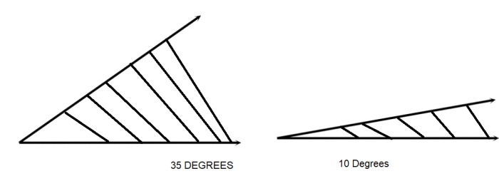
If you were driving a car up a steep incline the steeper the incline the steeper the incline the sooner you’d reach the top of the hill. That means for every degree increase in steepness greater heights are achieved. Here’s an example.

Therefore, a relationship exists between angles and linear measurement. If we shot an arrow at the moon and we were off in our aim by 1 second of arc we would miss it by more than a mile. (Boy, those little seconds can sure get in the way). 1 minute over an inch length has a rise of .000291”. The same 1 minute over 10 inches rises from a plane .002909” and over 1 foot the rise is .00341”.

I like to remember that 1 second has a rise of .000005” over 1 inch, this way it’s easy to multiply to get other values. Here’s one for you.

What’s the rise of 2 seconds of arc over 10 inches.

.000005” x 2 = .000010” x 10 = .0001” Approx.

It’s approximate because the value for 1 second is not exactly .000005” but really .00000484” (see chart) though not exact it sure is close enough for most applications.

As you can see in the chart the conversion goes both ways that is linear measurements can be readily changed into angular ones.

You may be thinking how is this done. Actually the conversions are done using trigonometry. Pages through define the process of conversion.

Ok, you’re ready, using the chart as a guide convert 15 seconds over 10 inches into linear measurement.

Next which is greater 22 degrees 15 minutes 10 seconds or 22 degrees 17 minutes 59 seconds?

Linear: Relating to, consisting of, a line: straight

Answers to questions page

  • .000727”
  • 22^ 17 59”

The manner in which these angles are expressed on a print is again similar to how we express time. Minutes are followed by a ’ and seconds by a ”. The change comes when we express degrees but then again another similarity exists this time between angular degrees and temperature degrees both are expressed using a bubble (o).

Putting this all together we can use the following example to get some practice.

15 o 7’ 42” is actually 15 degrees, 7 minutes, 42 seconds.

Recently there has been a trend to express parts of a degree in decimals. 45 degrees 30 minutes then becomes 45.500 degrees. We divided 30 minutes by 60 minutes and got .500

45 o 20’ would therefore become 45.3 o

45 o 59’ is the  45.98333 or almost 46 o

22 o 59’ 59” which is just a second shy of 23 degrees therefore 22.0031 o

If a full circle has 360 degrees then a semi-circle has 180 degrees. The supplement of an angle is the amount by which an arc or an angle falls short of 180 ^.

 SUPLLEMENTAL 40 Deg

Continuing along the same thought a complement is the amount by which an arc or an angle falls short of 90 ^.

Finally, angles can be right, acute, or obtuse. As per the following examples.

If you’re starting now to feel somewhat obtuse yourself, about angles it’s time to go on to the next chapter.

Accuracy, Resolution, Repeatability

I used to own one of those digital watches which told me the time of day to one tenth of a second. Then one day I realized it didn’t matter very much to me whether I was doing whatever I was doing at 3:15 or 3:15:1?42. So, I bought one of those European looking models that has a graduation every five minutes. I still tell time but not as closely as I used to.

Both watches are very accurate it’s just that with my current one I’ve got lousy resolution. Now I can tell that it’s approx. 3:15 give or take a minute or so. So, what’s suffered? Certainly not the accuracy but rather the resolution – that is the least significant digit that can be read, the digital watch had a LSD of .1 giving it as wristwatches go a high order of resolution. I’m measuring resolutions typically start of mechanical gages having resolutions of .001” (one thous) down to (.00001”) or lower. Don’t confuse resolution with accuracy. I could of course have a watch that resolves to .1 seconds but be “off” by hours. Accuracy is the difference read on the measuring device as it is? being compared to a standard. In the case of the watch the question is what time I do have as compared to the standard which is ticking away in Greenwich England, if it’s exactly the same time I’m accurate if I’m “off” some amount that’s my level of accuracy or inaccuracy – now I’m pretty sure my new watch is accurate but I’ve got a problem. It’s resolution is so coarse that I’ve no way of reading it. Determine how close or “off” I am from the standard.

Lesson #1- It doesn’t pay to have a lot of high accuracy in a gaging system if you’re no way of confirming it. By high resolution now just let’s say my watch is “off: by a full minute = what if I could better its resolution by placing grads on the face every 30 seconds. Now I’ve got lots of resolution, but the watch is still inaccurate. Because the resolution is better, I can see the inaccuracy better but it sure hasn’t helped make the time correct.

Lesson #2- Higher resolution doesn’t buy you much except higher resolution. Accuracy stands alone + hazed? Now what if I check the same watch every day + at the same time + one day it’s running a minute late and the next day it’s exactly on time. The problem we are then facing is one of repeatability. The watch that is a minute off but accurate can be set to the correct time and stay that way, but the one that fails to repeat leaves us with a problem which to reckon.

Lesson #3- I’d rather have a system that is off that I can reset than one that varies all over the place.

Lesson #4- You can never be more accurate than you are repeatable.

Metrology: Distance between two points

Millimeter: Thousands of a meter

Tenths – Micron = Millionth of a meter

Inch – Micron = Million of an inch

Microinch much smaller than micron

Tenth = 100 Microinch

Micron = .004 (HAIR)= .0001                 HAIR (.004)   = Microinch

                —————                             ——————

                  40                                              4000

1 Micron = 40 Millionths

7 Microns = 280 Millionths

.1 Micron = 4 Millionths

20 Microinches = 20 Millionths

4 Microinch = 1 Micron

2 Microinches = .5 Micron

Variable Gage Study

The number of operators (2 or 3) and the number of trials (2 or 3) may vary. Each operator measures 3 – 10 parts in random order for each trial. Data storage is optional. An option of tests are described:

  1. Gage Repeatability and Reproducibility

Gage repeatability is the variation in measurements obtained when one operator uses the same gage for measuring identical characteristics of the same parts; reproducibility is the variation in the average of measurements made by different operators using the same gage when measuring identical characteristics of the same parts. For each trial, have each operator measure parts in random order. Repeat the cycle, with the parts measured in another random order, for the number of trials required.

  1. Gage Accuracy

Gage accuracy is the difference between the observed average of measurements and the true average. Establishing the true average is best determined by measuring with the most accurate measuring equipment. Have one operator measure the same parts, using the gage being evaluated.

  1. Gage Stability

Gage stability refers to the difference in the average of at least two sets of measurements obtained with the same gage on the same parts taken at different times. How gage stability is determined depends on how often the gage is used between normal calibrations. If a gage is used intermittently, then have the gage calibrated before and after each trial to determine the amount of calibration change. If a gage is used constantly, then conduct another gage R&R study.

  1. Gage Linearity

Gage linearity is the difference in the accuracy values through the expected operating range. Conduct two accuracy studies, one at each end of the operating range.

TYPES OF GAGES

REVERSIBLE WIRE TYPE PLUG GAGES

A wire type plug gage is a plug gage comprising a gaging member of straight cylindrical section throughout its length held in a collect-type handle. This design is standard in the range above .030 to and including .760 inches. DU-WELL offers this type of gage up to 1.010. Sizes below .030 are available on requested note.

TAPERLOCK PLUG GAGE

A taperlock plug gage is a plug gage in which the gaging member has a taper shank, which is forced into a taper hole in the handle. This design is standard for plug gages in the range above .059 to and including 1.510 inches. DU-WELL offers taperlock gages in this range.

TRILOCK PLUG GAGE

A reversible or trilock plug gage is a plug gage in which three wedge-shaped locking prongs in the handle are engaged with corresponding locking grooves in the gaging member by means of a single through screw, thus providing a self-centering support with a positive lock.This design is standard for all plug gages in the range above 1.510 and including 8.010. DU-WELL shows up to 4.010 in the catalogue and will quote prices on larger sizes.

PROGRESSIVE SETTING DISCS

A master setting disc is a cylinder provided with insulating grips, used for setting comparators, snap gages, etc. There are three styles. Style 1 is a plain cylinder approximately twice the length of Style 3. The gagemakers’ tolerance is split plus-minus from the nominal size. Style 2 is two cylinders each approximately one-half the length of the cylinder in Style 1. Generally one cylinder is the “GO” master and the other the “NOT GO”. The gagemakers’ tolerance on the “GO” is minus and on the “NOT GO” it is plus. Style 3 is a plain cylinder approximately one half the length of Style 1. The gag makers’ tolerance is split plus-minus from the nominal size. The standard shows four designs – one for the range .105 to .365, one for .365 to 1.510, one for 1.510 to 2.510, and one for 2.510 to 8.010. DU-WELL lists size ranges for each of the three styles from .150 to 4.510, and will quote on sizes smaller and larger upon request.

PLAIN RING GAGES

A plain ring gage is an external gage of circular form employed for the size control of external diameters. In the smaller sizes it may consist of a gage body into which is pressed a bushing, the latter being accurately finished to size for gaging purposes. This design is optional in the range above .059 to and including .510 inches. Gages in sizes above 1.510 inches are flanged in order to eliminate unnecessary weight and to facilitate handling. An annular groove is provided in the periphery of the “NOT GO” ring gage as a means of identification.

SWIPE

(A lesson in Gage Repeatability and Reproducibility)

BY R.G. CHITOS

There used to be an old rule of thumb that if given a part’s total tolerance the gage selected to measure the part should have a resolution of 10% of the total part tolerance. Until recently no formal mention was made to this method. Today Gage R&R (Repeatability and Reproducibility) tolerances are  specified when ordering gaging inspection systems, as well as when applying these instruments to various production inspection tasks. The former method of purely relying on resolution made no provision for gage repeatability, gage accuracy or operator influence. Gage R&R methods and supporting formulas make an effort to resolve the issue by considering all of these variables.

The move to Gage R&R practice is welcome as it finally addresses some of the important areas that all good gaging practitioners have always known. The shortfall is that many of those who interpret the Gage R&R results do not fully understand the results. When specifying a 10% R&R, that is that the result of the test shows that the application of the specific gage tested does not consume more than 10% of the part’s total tolerance, many fail to realize that given standard practices and budgets 10% is not readily achievable. Many Inspection Managers will readily accept results of 20% of the tolerance and even 30% in some cases.

It is surprising how many companies have no idea what percentage of their total tolerance is being “eaten” by poor gages and poorer gaging practice. Routinely, when finally analyzed, gages and their application have consumed 50-60 and 100% of a parts tolerance.

The methods used to perform Gage R&R studies employ the use of several operators to take repeated readings on gaging masters as well as finished parts. The procedures allow for separation of operator reproducibility from gage error. This divides the blame, but in reality the gage supplier is generally saddled with the full brunt of the lack of adherence to the desired specification without regard to all of the variables that affect the final outcome. The very term GAGE R&R places the blame for whatever the problem directly on the gage.

SWIPE

Swipe is a mnemonic which stands for the following influencers of total measurement performance:

S- The Standard, is it certified and when, is it the proper class. For example in setting a bore gage to gage a 1” hole having a .00005” Bandwidth tolerance, if one were to use a class Y tolerance master, the uncertainty of the master alone could be as much as .0001” which is 20% of the total tolerance of the hole to begin with. The roundness of the master may be up to .00005” which is already 10% of the Gage R&R.

W- The Workpiece, every part varies, some more than others. Are the R&R operators aware of the variation within a part? Does the part have intrinsic taper, out of roundness conditions, surface finish variations etc. that can affect the measurements. Just by not taking measurements in the same place or zone on the part repeatedly can cause the R&R to suffer significantly. A .0001” out of roundness condition can consume 20% of the total part tolerance using the example above.

I- The Instrument itself obviously has linearity, and repeatability characteristics. Whatever they may be, clearly they add to the gaging uncertainty. In addition, certain instruments are more prone to operator loading, use, and care.

P- The Personnel and their ability to adapt the gage to the part is an ever important factor. Surely the gages vulnerability to operator influence can be considered the gage’s fault. However one should not discount the variation in touch and experiment that the operator brings to these tests. With some operators and their influence there may be no gages or inspection equipment made to perform the measuring task at hand. Surely an enigma, but best handled when best understood.

E- The Environment. Parts that are dirty, oily, or hot or even cold are poor candidates for R&R testing methods. They may represent the real world conditions but offer no stable ground on which to buyoff on a gages ability.

So there you have it, the SWIPE scenario. The answer may very well be that considering all of the variables, the only one that can be rectified is the gage’s intrinsic accuracy and repeatability. In this case it becomes necessary to obtain gages of a higher order. This may mean changing from Mechanically applied hand tools to Electronic or Air Gage tooling. These tools permit higher resolution and linearity and repeatability. They limit operator influence and offer output to SPC and signaling modules. The cost may increase but the value per item measured makes these types of tools irreplaceable.

Gage R&R, while an important measure in the measure of the measurement system requires careful consideration in its application.

www.willrich.com

4 Reasons Gage Calibration Is Important

Equipment calibration has always been a necessary part of maintenance. Regardless of the type of gaging equipment, calibration is a must for the purpose of maintaining quality. The accuracy of measurements taken with gaging equipment can start to degrade over time due to wear and tear brought on by extreme temperatures and harsh conditions. Without regular calibration, it can result in parts being made with incorrect dimensions. This can lead to costly rejections and repairs, as well as a decrease in product quality.

The following points will further explain the reasons gage calibration is important.

Maintain Accuracy

Gaging equipment is used in the field of engineering and design for measuring parts. Using gage devices is essential to get dimensional information and determine whether a part or an object meets a standard or a system. As mentioned, the accuracy of a gage device can degrade over time. Hence, to ensure that it provides accurate readings and is performing its job correctly, regular calibration is a must. This process verifies and restores the accuracy of the gage as needed.

Quality Assurance

Poorly calibrated gage creates inefficiency and can significantly impact quality and safety. When there’s no accuracy, the rate of rejected parts will be high. On the other hand, accurate gaging devices improve product quality. Also, they help with quality control as they can quickly spot parts that do not meet standards earlier in production. It is important to calibrate devices in order to maintain the integrity of readings and the accuracy of measurements.

Compliance

OEMs these days are demanding suppliers and companies to establish calibration programs for their measuring equipment. According to ISO 9000, companies should continuously examine their programs for weaknesses and make improvements. Meanwhile, ISO 9002 states that suppliers must calibrate equipment and devices used for inspection, measuring, and testing at prescribed intervals against certified equipment. To help them stay compliant, some large companies hire specialists in calibration methods while others use calibration services.

Keep the Company’s Reputation

If a company doesn’t detect rejected or poor-quality parts, its customers soon will. These errors or inaccuracies can lead to costly consequences, including damaging a company’s reputation. To protect the company’s image, gage calibration is necessary.

Tips on Gage Calibration

How to choose the right calibration company? Take note of these tips:

  • Ask for Certificates – When choosing a calibration house, make sure that they provide you with a certificate of calibration. This is important for compliance. The certificate must include the following information:
    • The serial number and description of the gaging equipment
    • The serial number of the gage used for the test
    • Tolerances of the data or level of uncertainty of the calibration
    • A statement of traceability to nationally recognized standard
    • The serial number of the NIST test where the house based its standards
    • Reference temperature
    • Date of calibration
    • Signature of the technician
    • Test results

The house must also indicate that the gage was adjusted or recalibrated in the certificate.

  • Look for Documentation – ISO 9000 requires calibration houses to document their methods and procedures in a manual. You should ask about them before enlisting their services. If unavailable, find a different calibration house.
  • Consider Reputation – To date, there haven’t been any standards for calibration houses. That’s why you must be extra cautious. Reputation can be a good starting point when choosing a company. Still, don’t be afraid to ask a lot of questions to gauge the company’s experience, expertise, and reliability.

How To Measure Small Bores

A bore gage is an instrument used to determine the inside diameter (ID) of a hole, a cylinder, or any spherical object. Bore gages differ in measuring techniques. Although, a typical bore gage features anvils that expand until they touch the inner surface of the bore. Measuring bores is an essential step when assembling or building an engine. It is also done as part of equipment routine maintenance of equipment to check for wear-out parts.

Is There a Different Method for Measuring Small Bores?

For many years, our experts have tried air gaging as well as back pressure for measuring small bores that are below 1 mm. This method can be instrumental in taking measurements of small bores. However, it’s not the best tool as it provides details about flow area and, not form information. The problem with these bores in question is that they are too small. It is possible that there is no other economical way to measure small bores other than air gaging.

If the bore measures more than 1mm, then there will be various bore gages in the market to use. You will find gages that measure 1 mm – 20 mm bores.

Can You Use a Plug Gage for Measuring Small Bores?

The short answer is no. To get the bores’ sizes and deviations, this type of mechanical bore gages use comparison. However, they don’t work the way fixed plug gages do. They neither need a ground cylinder nor a sensitive contact when making a comparison of a master to a bore. Instead, they use the plug’s mechanical transfer as the only probe for measurement. Because centralizing plug is not present, the probe is rocked inside the bore. This way, it can measure its diameter.

In other words, a plug gage is used to check if the internal diameter of a bore falls within the specified tolerance. Meanwhile, a bore gage simply measures the size of a bore.

This method is actually similar to adjustable bore gage technique that many people are familiar with. However, the small-probe gage can take the measurement of bores that are significantly smaller as compared to the holes that an adjustable bore gage usually measures. The former gage can be used for different kinds of holes or parts. That means, a user doesn’t have to use different tools for their measuring tasks.

Although, one must take note that its measuring range is limited. A small-bore probe that has a 1 mm nominal size measures 0.95 mm – 1.15 mm bores. A probe with a 10 mm nominal size measures 9.4 mm – 10.6 mm bores. Lastly, a probe with a 20 mm nominal size measures 19.4 mm – 20.6 mm bores. Nevertheless, they have repeatability and a measuring range accuracy of 1%, which are great advantages.

How Does This Type of Probe Work?

As mentioned, a small-bore probe work like a fixed plug gage, but with a few differences. Its sensitive contacts change to determine the bore diameter. As they do that, the size is being measured which will be seen in its indicating device. Depending on the small-probe gage, the indicating device could be a digital indicator, a dial, a comparator, or an LVDT.

Like any gage, this small probe gage needs a setting master. The master should be placed on the probe and then rock the plug. While rocking it, the user shall observe the indicator readout until it reveals the smallest value or reversal point. Next, the user shall set it to zero. Sometimes, it is also set the point to nominal size. Only after these steps shall the user start measuring the bore to find its diameter.

Fortunately today, there are digital indicators that simplify the process, thanks to their advanced features. They now have a memory feature. That way, the user doesn’t have to keep remembering the smallest value while measuring bores. Thus, speeds up the entire process.

Small probe gages offer a precise way to measure bores ranging from 1 mm – 5 mm. They provide the users with the necessary information for tight tolerance bore measuring applications.

Introducing the Marameter 844 K Bore Gage System from Mahr Metrology

Marameter 844 K self-centering dial bore gage system is ideal for measuring bores ranging from 0.95mm – 1.55 mm. A self-centralizing gage is among the basic types of bore gages, which include the go/ no-go plug gages, indicating plug gages, and non-self-centralizing rocking gages.

Why use self-centering dial bore? Rocking the adjustable gage takes a lot of effort. The user has to develop the right skill through performing the method conscientiously. A poorly trained operator is likely to produce inaccurate measurements. The greatest benefit of this type of gage is that it eliminates the need of “rocking” to center the gage in the bore. It also avoids operator influences and doesn’t require a lot of training. A user can easily learn how to operate it.

Our Marameter 844 K self-centering dial bore gage system has been a part of the Marameter hole measuring system for many decades. It has been tried and tested and has undergone innovative upgrades for maximum linearity accuracy. You can use this for determining the diameter and testing the roundness and tonicity of bores. It can also be recommended for testing batches. Our product comes with a measuring holder 844 Kg, a probe, and an expanding pin. It is packaged in a quality wooden case.

For more than 50 years, Willrich Precision has been dedicated to bringing high-precision gear, measuring tools, and metrology products. Our team strives to ensure top quality products and services. We are an ISO:9001:2015 company that constantly is in the mission to help businesses streamline their measuring processes while taking their quality assurance to a new level.

Our company is a proud partner of Mahr Technology, a five-generation family business that operates globally. For high-quality measuring instruments from Mahr that you can use for analysis and evaluation of workpieces, visit our website. You can also contact us if you need quick and reliable support from our service experts.

Top Tips To Check For Balance And Centralization Problems

One of the advantages of using air gages is that there is little contact between the tool and the workpiece. In fact, such tools are typically referred to as non-contact tools. But, strictly speaking, this is not entirely true. Air gage tools do come into contact with workpieces, and this may be reflected in the fact that they do suffer wear and tear over time. The progress of this degradation may be significantly slower than that of contact gages but eventually, it is bound to happen.

How Wear And Tear Leads To Centralization Issues

When your air gage tool is sufficiently worn out, the clearance between the workpiece and the gage will usually be greater than it was designed to be. This in turn leads to centralization problems where the air gage tools measure a chord of the workpiece in question rather than measure the diameter of the part. Centralization problems may also arise if the centerline of the jet is not aligned with the plug centerline. As the tool degrades and the space between the bore centerline and the chord increases, the centralization errors become bigger and bigger.

Obviously, machine operators will allow for some centralization error, but this depends on how much leeway their process allows them to. With looser tolerances, these kinds of errors don’t pose much of a problem. However, with tight and precise machining, this becomes a problem for the machine operator.

Understanding Balance Errors

Unlike centralization errors, balance errors happen when the orifices and cavities in the air gage jets become clogged or are damaged by misuse, or as we saw earlier, become worn-out unevenly. This is because for your air gage to work properly, it is important for all the jets to have the same orifice diameter and recess. Anything that changes these parameters throws your air gage tool off-track.

The next question then is how you can spot this wear and tear and what you can do about it. There are two main approaches that you can use to do this.

Visual Inspection

Though not always possible, you may be able to see contaminants that may be clogging up your jets. This will of course depend on the type of tool you are using, its size and so on. This is part of the reason it is essential to keep your gages as clean as possible, as well as the workspace that you use them in. However, visual inspection may not always be possible. Even in the circumstances that it is, it may not always be possible to understand just how badly the problem is affecting your measurements.

In order to get a more accurate picture of the problem, try the second approach.

Using A Master

This approach is based on the fact that for most air gage tools, wear and tear tend to follow a fairly predictable pattern. With gages that are hand-held, the wear is often around the plug’s circumference and tends to be relatively even. For these, secure the gage horizontally, then take a master reading. Having noted the reading, take the master and place it on the lower surface of the plug. Again, take another reading. If there is wear and tear of the plug, the readings will be different. Generally speaking, if the difference between the two is more than 10% above the acceptable tolerance, you may have to replace the plugs, or the tool all together.

How Do Air Straightness Plugs Work?

Air straightness plugs are slightly more sophisticated than conventional air plugs, but still have all of the benefits of a normal air plug: they are simple to set up and operate, and they produce highly accurate results.

Design

A conventional air plug includes four measurement jets, two in the center and two at the ends, arranged in two groups. The plug’s structure enables it to see both ends of the bow situation. The exact location of the jets in relation to one other is not governed by any standards, as is the situation with squareness or taper tests. There are no ratios concerned, either.

The air nozzles at the plug’s extremes are designed to check for non-straightness, which is normally defined for the bore‘s whole length. However, before we can grasp the way in which a straightness plug functions, we must first look at the different combinations of jets that are common in air tooling.

Differential Measuring

A differential measurement system is what is associated with a two-jet plug. Picture a two-jet gas plug with a zero readout within a master ring. Adjust the plug such that one of the jets is positioned on the ring’s side. This raises posterior force on one jet while lowering it for the other.

A four-jet system is an expansion of the two-jet gas plug. Four jets are combined together in this case, and in the event that the plug is shifted in any manner, an aggregate reading is taken once again. The four jets each detect four changes in pressure and sum them up. The total—and the readout on the indicator—changes whenever any of the recorded dimensions fluctuates.

On the plug, the 4 jets are usually at equivalent levels or planes. The 4 jets may theoretically be moved individually anyplace along the plug, and in the event that they are situated at ninety degrees relative to each other, they would measure the bore’s mean diameter. The 2 jets on top are counterbalanced by the 2 jets on the bottom, resulting in no change in the show. The aggregate pressure fluctuates if the bore is not completely straight, and the differential would be displayed on the instrument.

Dynamic Measuring

The display gives a number in the event that the straightness plug is merely put into the bore. The key question is what that figure implies. Whenever the jets are aligned with the bow, according to the orientation, they obtain their maximum or minimum reading. When the plug is rotated one hundred and eighty degrees, the outer and inner jets switch roles and show the same value, indicating that the plug is in a differential state.

However, when the plug rotates one hundred and eighty degrees to explore the bore, the sets of jets would have a peak clearance, followed by a minimum clearance, generally at ninety-degree angles to one another. As viewed along the whole extent of the plug measuring length, the difference between the greatest and minimum value would be the out-of-straightness state.

Why Concentricity Measurement Is Important In Manufacturing

In manufacturing, the design of each component contributes to and determines the usefulness and effectiveness of the end product. If concentricity is not measured and remedied before the product is sent into manufacturing, it could create a chain reaction that will cause serious issues later down in the assembly pipeline. This is highly cost-ineffective as it would incur high costs for your project. Therefore, concentricity must be measured and ensured of the right value. In addition, all the parts should work cohesively together before the product design is sent into production.

What Is Concentricity?

Concentricity is considered a type of complex tolerance, and its value is calculated to determine to which extent the geometric shape would be closest to the ideal form. First, median points of the spherical and cylindrical parts are established. Then, when the piece is concentric, the thickness of the internal and external walls will be consistent and equidistant. This would be critical in ensuring that the dimensions of the finished products will not exceed the manufacturing tolerances, which helps in fitting parts accurately in their intended application and will prevent any unintended vibratory movement and resistance.

What To Choose: Concentricity or Total Runout?

Concentricity is measured or calculated using a process also known as total runout. The two types of measurements are similar, but they vary in specific components. Both are determined using an axial orientation or alignment and also pose the challenge of being difficult to calculate. The median points are established in a spherical and circular axis in calculating concentricity. At the same time, the total runout is determined by fixating a datum point and then turning the part around to ensure median points fit within the tolerance zone.  

How Is Concentricity Usually Measured?

There are three ways concentricity is usually measured to ensure minimal error in the manufacturing process. The first is using a sample drawing to map out the axes of the cylindrical or spherical shape, and the aim is to ensure the median points are accurate coaxially. The next most commonly used method is using an equipment called the dial gage.

The dial gauge is placed on the circumference’s vertex of the product, where the axis of the tolerance would be determined. Then, the product would be rotated, the maximum and minimum runout values would be calculated, and the specified circumference would be measured. This difference in maximum and minimum values would be considered concentricity.

The last way concentricity is measured would be through a coordinate measuring machine, where the circle of the plane is calculated instead of coaxially. Then, the stylus is placed at the datum circle’s measurement point and the target circle’s measurement point, where the concentricity is measured.

Why Choose Willrich Precision?

Willrich Precision offers over four decades of inspection, metrology, and gauging experience. We  provide a vast range of services and products to clients, including advanced metrology technology and measurement equipment for vision and laser systems. Furthermore, we take great satisfaction in establishing ourselves as a pioneer in measuring instrumentation technology and, as a result, can serve a diverse spectrum of clients from various sectors. Every client connection is given top priority. That is why we offer you a free consultation and access to our team of seasoned professionals that are highly competent and can assist you.

Please contact us at [email protected] now for more information about our inspection and metrology services and products!

What’s The Difference Between Runout And Concentricity?

Concentricity limits how asymmetric the shaft will be in relation the datum axis. If the shaft is oval without being a perfect circle, it can still considered concentric. By imposing diametrical symmetry, it regulates mass balance about the datum axis. It does not influence the size or taper of the shaft. At the same axial location along the datum axis, it compares the radius on one side of the shaft to the radius on the other side of it.

Runout limits how the unbalanced circular or spherical shaft relates to each datum point located along the shaft. In the scenario where the shaft may be perfectly circular or round, if its axis deviates from the datum point, it will be considered a runout. However, the shaft size is not caused by the runout and runout has no control over the other forms, but only affects the variance of the radius-to-datum in each location.

How Similar Are the Results?

Position specifies the volume in which the shaft’s surface must remain. The shaft surface’s volume must remain in is determined by the shaft’s maximum permissible diameter alongside the tolerance of the position. The volume the axis must retain the tolerance of position and the maximum material tolerance allowed. The surface approach is the one to use. Any approach should produce relatively comparable results for an actual component, and they are also mathematically equivalent.

What Is the Difference between Runout and Concentricity?

Concentricity is the circular form of geometric dimensions and tolerance symmetry, while the runout combines both circularity and concentricity. The runout will equate to concentricity if the component is perfectly spherical and round. However, what is circularity in this text? Circularity would determine the form, orientation, and location and usually cannot be referenced to the datum axis. However, the only exception would be when the size tolerance is tighter than the runout tolerance.

Concentricity considers how a cylindrical shape is positioned on a theoretical axis. In contrast, the runout considers how the target deviates from the dimensions of a circle when it is perfectly positioned on the rotation axis. However, when the part is measured using a similar cross-sectional plane, this is considered a case of coaxiality, as the internal diameter and outer diameters of the shaft or tube are compared.

Why You Should Choose Willrich Precision

Willrich Precision has over four decades of experience in inspection, metrology, and gauging. Clients may choose from a wide range of services and products, including modern metrology technology and measuring equipment for vision and laser systems. Furthermore, we take great pride in establishing ourselves as a leader in measuring instrumentation technology, allowing us to service a wide range of clients from numerous industries. Every client connection is treated as our first priority. That is why we provide you with a free consultation and access to our team of highly qualified individuals that can assist you.

For more information about our inspection and metrology services and products, don’t hesitate to contact us at [email protected] today!

What Does Concentricity Mean?

Concentricity is a value used to calculate the extent to which a geometric shape in CNC (Computer Numerical Control) matching is closest to its ideal form. This measurement is commonly taken in CNC machining to ensure high precision and quality during the production stage to ensure manufactured parts fit perfectly together and minimize errors. There is value to measuring the concentricity of a product during CNC machining, including a greater assurance that the dimensions of prototypes will not exceed their manufacturing tolerances. In this article, we dive deeper into the meaning of concentricity and how it is used in metrology to expedite the product development pipeline.

Why Do We Need to Measure Concentricity?

The bottom line in the pursuit of product development is to ensure that workpieces do not vary too from having perfect symmetry, especially when a machine processes it. In many cases, deviation from having the ideal symmetrical balance can be costly, resulting in material waste and higher production costs. Most importantly, it will create flaws and issues later in the production process. Therefore, it is usually measured in an axial or radial orientation to examine the extent of the error in the different dimensions. However, as this process is considered complex and difficult to implement, it is only used in specific situations and when needed.

How to Measure Concentricity?

The value of concentricity is usually calculated using the two diameters of the hole – one for the hole and the other for the shaft. They signify the outer boundary and the inner line, respectively, and both are necessary to examine the deviation in surface measurements. Additionally, depending on the company’s protocols, they can be measured in imperial units (inches) or metric measuring (millimeters). As mentioned before, measurements in CNC machining are made in the axial or radial orientation; therefore, three methods are considered relevant in this aspect.

  1. Radial Error – The measurement variation between the feature’s center on one side and the corresponding point on the other.
  2. Axial Error – This is calculated by subtracting the distance from machine zero to a datum line and then calculating the deviation from this line at two locations along its length.
  3. Overall Accuracy – This value is obtained by adding radial and axial errors together, or it can be pre-calculated (empirically) because certain machines provide complete concentricity

A Common Challenge in Concentricity Measurement

The dial indicator is one of the most common ways in which engineers measure concentricity and it is usually done in both directions. It will measure at a 90-degree angle to the longitudinal axis and at a one-sided offset. However, it poses the challenge of requiring sufficient space of up to 18 inches to inset the spindle tip of the equipment. Additionally, you will need to be extremely cautious of any accidental breakage or deflection of the rotating components during the measurement process.

What We Offer

Here at Willrich Precision, we have almost half a century of experience in the metrology, gaging, and inspection fields. We offer a great variety of products such as basic measuring tools, metrological technology, and equipment like vision systems, laser systems, and micrometers. We are a pioneer in measurement instrumentation, and we are dedicated to helping you make informed and intelligent decisions for your business operations like CNC machining.

For more information about the product and services Willrich Precision Instrument offers, please do not hesitate to contact us today!