Willrich Precision Instruments: Calibration and Precision Measurement Solutions
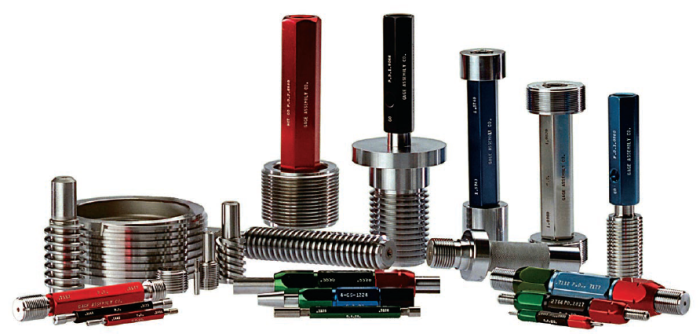
Since 1971, Willrich Precision Instruments has been a trusted provider of precision measurement solutions and calibration services for decades. Known for its expertise in gauges, CMM inspection, and ISO/IEC 17025 accredited calibration, we have become a reliable partner for industries that require accurate and traceable measurements.