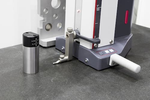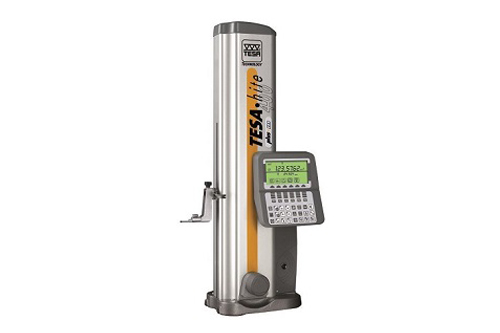
Digital height gages are used to perform a
variety of measuring tasks quickly and reliably. Digital height gages are made
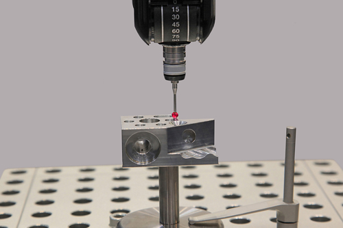
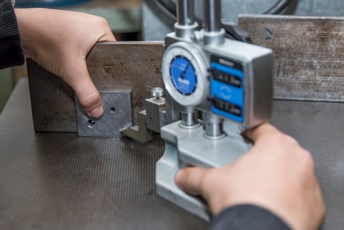
up of a base plate with a measuring station and a control display. The
measuring station is designed to measure one-dimensional coordinates
vertically. For this reason, digital height gages are great for measuring
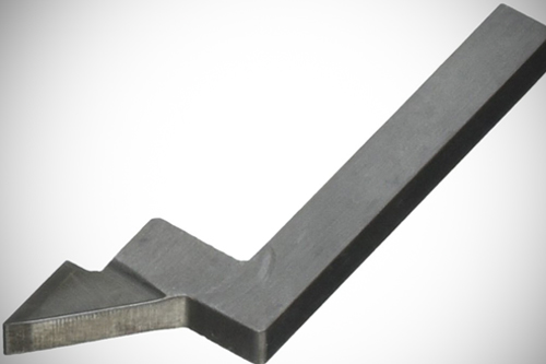
distances between two points on an object or for measuring diameters. Over the
years, operators have discovered other ways of using digital height gages. For
example, if the object being measured is tilted to an angle of 90 degrees, then
measurements can be taken at this angle as well. Here are some tips on how best
to use these useful measuring tools.
Keep
the Gage and Work Surface Clean
Before using a digital height gage, ensure that the work surface, the contact probe, and the space around the equipment are clean. This is because dirt and particles on the surface where the gage rests or on the contact probe can affect the measurements taken by the gage. It is also important to ensure you zero the gage before you use it. This is done by switching the gage on and letting it set its reference location. After a minute or two, repeat the process again and compare the first result and the second.
Mind
the Temperature
Sometimes, operators using digital height
gages convey their body heat on to the instruments. This causes various
elements of the tool, such as the base plate, test piece, or the stylus to heat
up. This, in turn, produces inaccurate readings due to heat expansion. Operators
should be careful about what they touch and how long they remain in contact
with the elements of the gage. It is also recommended that operators use gloves
when touching the test piece.
One should also avoid placing the digital
gage anywhere near a draft or direct sunlight to avoid cooling or heating up
the gage elements. It is also important to avoid testing parts that have been
transported in a cold or hot facility. Experts recommend letting them ‘rest’ in
ambient temperature for a while before using the digital height gage to measure
them.
Keep
the Gage Working Properly
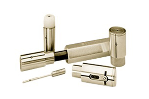
It pays to constantly inspect the gage for deflections
on the contact points where they touch the part. This happens when the contact
point is long and this can affect the accuracy of the measurements that are
taken. When deflection is noticed, one has the option of building a
reinforcement bridge on the contact so as to minimize the effect of the
deflection
Other Tips
Machine operators can improve the measurements they take by avoiding radiators in the proximity of the digital height gage. It is also important to use the air bearings to position the height measuring instrument. If you are using a digital height gage with a motor drive, one can improve the accuracy of the measurements by using a constant gaging force when the test piece is being measured or inspected.