Which Applications Require the Use of Vernier Calipers?

Vernier Calipers

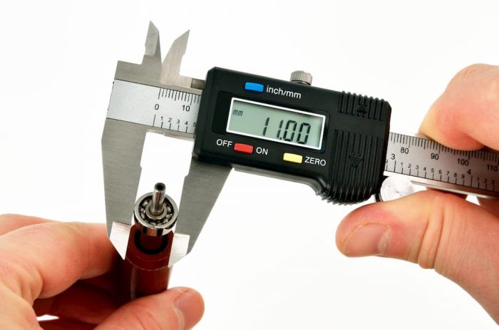
A vernier caliper is a measuring instrument
that can measure the internal and external dimensions of an object. These
useful instruments can also measure object depth. Vernier calipers have a jaw
that is fixed and one that moves along a well-calibrated scale. This moving jaw
is capable of measuring accurately to within a hundredth of a millimeter. Vernier
calipers are popular due to their highly accurate measuring capabilities. Here
are some of the applications that these highly popular instruments are used in.
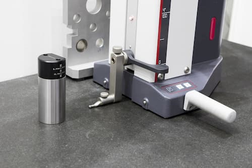
Machine
Shops

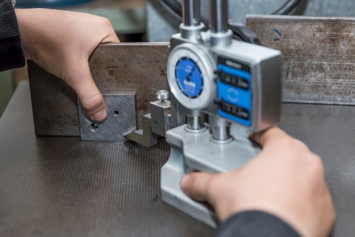
One of the places that you are likely to find a vernier caliper is a machining shop. Most industries that make precise components, such as the auto industry and the aviation industry, use vernier calipers to ensure consistency in the parts that they produce. To use the car industry as an example, the springs that are produced by the auto assembly factory must all be very precise otherwise the car will be unstable. Vernier calipers help ensure consistency of parts in such industries.

Medical
Instruments

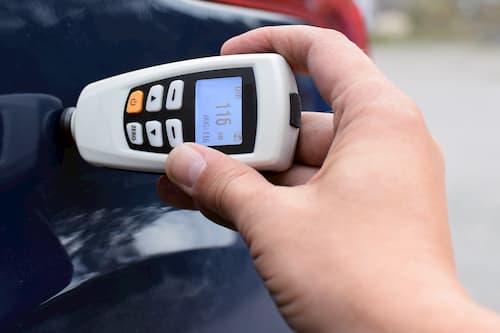
Industrial processes that produce medical
equipment must also adhere to very precise measurements. It means that quality
control experts in such manufacturing processes must measure precise dimensions
of parts produced and ensure that all of them adhere to these standards.
Mistakes in length or depth of some of these precise instruments would
inadvertently lead to injury and even loss of life.
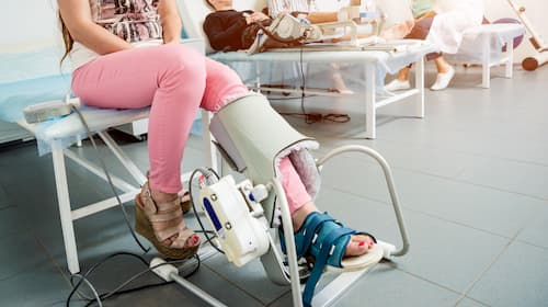
Research
Applications

Research laboratories make use of vernier
calipers to understand the effect of heat and other reactions on the elements
that they are testing. Many research processes seek to understand the effect of
certain reactions and one of these reactions is expansion or contraction of the
test pieces. When researchers need to understand these effects at very precise
dimensions, they use vernier calipers to measure the test objects before and
after the reactions.
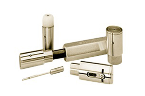
Locksmithing

Locksmithing involves working on very
precise locking mechanisms. For example, designing safes requires parts to
interlock in very precise patterns and this requires that these parts are
measured to very precise dimensions. For this reason, locksmiths and safe
makers use vernier calipers to ensure that the parts they are making adhere to these
standards. Keys that are used to open locks and safes must also be very
precisely tooled and vernier calipers are immensely useful in ensuring that
they adhere to the required standards.

Educational
Institutions

Another place where one is likely to find
vernier calipers in use include colleges, universities, and schools. Here,
vernier calipers are used to help students perform science experiments and work
as a teaching aid for various subjects.

When all is said, getting high-quality vernier calipers and using them properly is a first important step to getting the most out of these important instruments. At Willrich Precision Instrument, you are guaranteed a wide range of high-quality vernier calipers that can be used in all these applications and more.

Product Spotlight: Starrett Height Transfer Gages No. 252 Series

Starrett Height Transfer Gages No. 252 Series

Height gages are designed to measure the height of various types of workpieces. This measuring instrument typically comprises individual components, such as a slider, a measuring stylus, a measuring scale, a beam, a reference plane, and the instrument base. Chances are you might have heard of height transfer gages.

These gages are ideal for use with electronic amplifiers and/or test indicators, allowing technicians to accurately transfer height settings from height gages, gage blocks, and other standards. If you are looking to get Starrett Height Transfer Gages No. 252 Series, you have come to the right place. Learn more about the product in this spotlight!

About
Starrett

L. S. Starrett Company is a reputable
American manufacturer of precision measurement tools and instruments. Their
products are used by a wide variety of tool and die makers, as well as
machinists across the globe. Founded in 1880, the company was the brainchild of
Laroy Sunderland Starrett, who was an inventor that had sharp business acumen. With
over 130 years of experience in the field, Starrett has set a high standard for
fine precision tools; they have been coined as the World’s Greatest Toolmakers.

Today, Starrett employs approximately 2,000
employees and has eight manufacturing locations worldwide, including five in
the United States, China, the United Kingdom, and Brazil. The full-line
precision tool company continues to design and manufacture tools that are
essential for assembling, forming, cutting, and measuring workpieces. Starrett is
also traded publicly on the NYSE.

Features
of Starrett Height Transfer Gages No. 252 Series

Here is a quick look at some of the top
features of Starrett
Height Transfer Gages
from the No. 252 Series:

  • Lockable slides (comes with
    thumb screws)
  • Multiple ground and lapped pads
    enable smooth and stable movement on the surface plate
  • Adjustable mechanisms located
    in the base
  • Indicators and columns are
    isolated (not affected by hand pressure or heat)
  • Has extreme rigidity
  • Vibration-proof
  • Delivers precise and repeatable
    readings
  • Rectangular box-type hollow
    column
  • Offers ease of movement and
    sure-grip handling
  • Places to hold electronic gage
    heads and test indicators
  • Base knobs enable fine vertical
    adjustment of the slide unit

Get Starrett
Height Transfer Gages No. 252 Series from Willrich Precision!

At Willrich Precision, our customers can purchase a wide range of height gages and other related instruments at the most competitive rates, including No. 252 Series Starrett height transfer gages. We have been in business for more than 40 years and understand the intricacies of metrology, gaging, and field inspection better than our competitors.

Willrich Precision provides a hassle-free online shopping experience for all of our valued customers. Whether you are looking to get height transfer gages for aerospace or medical applications, we have got your back. Our height gaging experts will ensure that you purchase the correct products.

If you wish to know more about Starrett
Height Transfer Gages No. 252 Series, do not hesitate to talk to a Willrich specialist today!

Top Tips For Handling Digital Height Gages

digital height gages

Digital height gages are used to perform a
variety of measuring tasks quickly and reliably. Digital height gages are made
up of a base plate with a measuring station and a control display. The
measuring station is designed to measure one-dimensional coordinates
vertically. For this reason, digital height gages are great for measuring
distances between two points on an object or for measuring diameters. Over the
years, operators have discovered other ways of using digital height gages. For
example, if the object being measured is tilted to an angle of 90 degrees, then
measurements can be taken at this angle as well. Here are some tips on how best
to use these useful measuring tools.

Keep
the Gage and Work Surface Clean

Before using a digital height gage, ensure that the work surface, the contact probe, and the space around the equipment are clean. This is because dirt and particles on the surface where the gage rests or on the contact probe can affect the measurements taken by the gage. It is also important to ensure you zero the gage before you use it. This is done by switching the gage on and letting it set its reference location. After a minute or two, repeat the process again and compare the first result and the second.

Mind
the Temperature

Sometimes, operators using digital height
gages convey their body heat on to the instruments. This causes various
elements of the tool, such as the base plate, test piece, or the stylus to heat
up. This, in turn, produces inaccurate readings due to heat expansion. Operators
should be careful about what they touch and how long they remain in contact
with the elements of the gage. It is also recommended that operators use gloves
when touching the test piece.

One should also avoid placing the digital
gage anywhere near a draft or direct sunlight to avoid cooling or heating up
the gage elements. It is also important to avoid testing parts that have been
transported in a cold or hot facility. Experts recommend letting them ‘rest’ in
ambient temperature for a while before using the digital height gage to measure
them.

Keep
the Gage Working Properly

It pays to constantly inspect the gage for deflections
on the contact points where they touch the part. This happens when the contact
point is long and this can affect the accuracy of the measurements that are
taken. When deflection is noticed, one has the option of building a
reinforcement bridge on the contact so as to minimize the effect of the
deflection

Other Tips

Machine operators can improve the measurements they take by avoiding radiators in the proximity of the digital height gage. It is also important to use the air bearings to position the height measuring instrument. If you are using a digital height gage with a motor drive, one can improve the accuracy of the measurements by using a constant gaging force when the test piece is being measured or inspected.

How to Measure Counterbores And Blind Holes with Air Plug Gages

Air plug gages

Air plug gages are used to perform a
variety of tasks around the workshop. Some of these tasks include measuring
blind holes (also known as counterbores). An air plug gage is made up of a
cylindrical body that provides the guide for air jet positioning in the bore.
The nozzles that release the air are contained inside this body and this
essentially makes the air plug gage a non-contact measuring tool. The internal
nozzles also help to protect the air jets from being damaged. Air plug gages
also clean out the surface of the object being measured through the air jets,
leading to greater accuracy when measuring. So, how does one use these air plug
gages to measure blind holes?

Measuring
Blind Holes

When measuring blind holes with an air plug gage, one must ensure that the hole is free of any contaminants. Debris and pieces of wood or metal in the blind hole can lead to false readings from the air plug gage. One must also ensure that they are using the right size of the tool and that the gage is properly maintained. Typically, the air jets clear most of the debris away but it is useful to regularly inspect the nozzles to ensure that they are clean.

When using air plug gages, the gage will
automatically center itself in the hole being measured and reduce (if not
completely eliminate) the probability of angular error. This makes the gage easier
to use for operators who have limited experience in using air gages.

Take
Note of Tolerances

Apart from selecting the correct air plug
gage for the blind hole you want to measure, there are a number of things to be
on the look-out for. The first is to be aware of the tolerance that you are
measuring for.

Consider Different Surface Finishes

The other thing is to be aware of the
surface finish of the blind hole that you are measuring. Various surface
finishes can give different readings. This is because the air plug gages
measure the average of peaks and valleys that the air jets encounter.

Avoid Rushing to Take Measurements

The other thing to note when using air plug
gages to measure blind holes is to be patient with the readings. This is
because all air gages measure the backpressure created by the air inflows that
‘bounce off’ the part. If the backpressure takes a while to fill up, then
taking a reading immediately will probably give you bad results. This is
unlikely to be a problem when measuring blind holes in a simple workshop but if
this is happening as part of an automated manufacturing process, then bad
timing can result in wrong results.

Air plug gages are effective in measuring blind holes provided that they are used properly. Willrich Precision Instrument stocks a variety of high-quality air plug gages for all your precision measurement needs.

5 Golden Rules of Air Gaging

Air Gaging

Air gaging is a useful and effective method to measure hard to reach spaces such as small holes. Air gages have the additional advantage of being easy to use and are very flexible. Air gages are non-contact measuring devices and they are useful for measuring objects and surfaces that are extremely sensitive. When you are using air gages, there are some things that you need to keep in mind in order to produce the most accurate results possible.

Understand What You Are Measuring

Although this sounds obvious, it is not always the case that operators are clear on what they are measuring. Air gages can measure a variety of things including diameters, partial diameters, squareness, straightness, and more. Understanding what you want to measure will determine the usefulness of the data you get from the process.

Where Are You Measuring?

Air gages and the air jets that they use can measure a wide variety of spaces. One of the rules of air gaging is that the air jets have to be covered by the surface that it is measuring. When using an air gage, it is critical to understand that the air needs a path in order to accurately measure the dimensions of a hole. When you are measuring a blind hole, it can pose certain challenges.

Consider the Surface being Measured

When using an air gage, the finish (or roughness of the surface) will also have an effect on the reading that you get from the measuring device. If you were to use a contact-type gage to take the same measurement, there is a possibility that the two readings will be completely different.

Backpressure May Delay the Process

For an air gage to work properly, it is essential for the air channels and the air pipe in the machine to fill up due to the back pressure. This back pressure is created when the airflow from the jets are restricted by the part being measured. If the air pipes are long, this process can take a while, and in certain applications such as high-speed automated gaging, it might lead to incomplete results. One way to solve this problem is to bring the converter as close to the surface being measured as possible to reduce the length of the air pipes. The second way is to ensure that the air in the tool does not flow out of the part between measurements. This means that the air hoses take a shorter time to fill up as they would already have a significant amount of air from previous measurements.

Altitude Matters

The height of your location plays a part in the performance of your air gage. This is because air is thinner at higher altitudes and this can affect the performance of the equipment. Since most air gages are custom made for specific tasks, ensure that you ask your supplier to take the altitude of your location into consideration when calibrating the machine. This is also something to keep in mind when moving the equipment from one manufacturing plant to another.

How Does Dimensional Data Collection Improve Moldmaking Operations?

Dimensional Data Collection

Moldmaking processes in the past have often relied on CMM machines to get the precise dimensions of the mold correct. Coordinate Measuring Machines use a probe for data collection. This probe typically moves through various axes and each point of contact is recorded. The probe will establish a certain amount of contact points with the object, build a sufficient dimensional database, and develop a profile of the surface. When making molds, the ability to define 3D shapes becomes essential. This is why automated measuring is most suited for this role.

Scanning Capabilities

For a CMM to define a complex shape in 3D, it is critical for it to be able to take in large amounts of data at one go. This is to enable it to build an accurate picture of the object that is being scanned. This also means that the moldmaker collects the data he or she needs quickly and accurately. This data can then be used in design programs such as CAD or can be stored for future reference.

Continuous Scanning

Traditional CMMs use a process that is known as stitch scanning to collect the data that it needs to define the surface. In this case, the probe makes contact with a part of the surface and then is lifted to reinitiate the contact at another point on the same surface. This process works effectively for surfaces that are fairly even and don’t need multiple data contact points for the CMM to define the surface. When it comes to moldmaking, large amounts of data are needed so continuous analog scanning works better here. The probe is always in contact with the surface and the data stream remains uninterrupted.

New Technology

New technology is redefining how CMMs scan and collect data. Areas of improvement lie primarily in three areas namely the CMM controllers, data sensors, and software.

Controller Technology

Under this category, new technology is making it possible for controllers to control the probe more autonomously and react to unexpected features on the surface. Modern controllers are able to change the direction of the probe and reformulate their calculations to incorporate new features that are encountered along the way. Controllers are also moving in the direction of greater autonomy. This means that machine operators can start the scanning process, and the controller will execute the scan without requiring any further input from the machine operator.

Sensor Technology

CMMs are shifting away from contact sensors to non-contact sensors. This is driving significant improvement in scanning speed, as well as allowing the device to be used on materials that may otherwise be damaged by a contact probe. Other improvements in sensor technology include the rise of CMMs with multi-sensor capabilities. This creates room for more flexibility as the CMM can perform both tactile scanning and precision single-point scanning.

Software Improvements

This focuses on how information collected by the new CMM machines is processed. Advances in software have seen user-friendly interfaces with commands in English rather than complex programming languages. This makes it possible for operators with no knowledge of coding to analyze data quickly and easily. Modern CMM software also allows for greater precision. A good example is a point-smoothing function that enables the machine to distinguish between surface features and other aberrations such as dirt and scratches. Machine operators can also define the limits of the search and mark features that do not require scanning (such as holes) so the machine avoids scanning them.

Reaching New Heights with Digital Height Gages

Digital Height Gages

Digital height gages are devices that are used to measure the height of objects. As part of the process of measuring heights, most digital height gages are capable of marking the object itself in order to record the reading. Outside precision tooling, similar tools are used in hospitals to measure the height of patients. Height gauges are used in a variety of processes and typically measure height along a single vertical axis. There are three main types of height gages namely vernier, dial, and digital height gages.

Vernier and Dial Height Gages

Vernier scales are finely tooled height gages that rely on a base and a vertical measuring scale. The vertical measuring scale is calibrated, and using an attached Vernier scale, readings can be made off the object being measured. Dial height gages, on the other hand, work in the same way as vernier height gages except for the fact that height readings are made on a dial display that’s attached to the machine.

Digital Height Gages

Digital height gages are the latest in the evolution of height gages and come with many new features that help improve ease of use and accuracy of readings. Here are some of the ways that digital height gages that can raise the standard of your work.

  • Better accuracy

Digital height gages can significantly improve the accuracy of your measurements. This is because they come with greater stability and weight, making it hard for them to slide on the bench top. Digital height gages are now able to measure diameters and thicknesses of objects.

  • Distance between centers

Digital height gages are now able to measure distances between two centers. They do this by having the ability to record the highest and lowest points between a sweep and thus can calculate the distance between these two points. These recordings are stored within the machine’s memory and can be retrieved with a simple push of a button.

  • Diagonal measurements

These gages are capable of measuring diagonal measurements. You can do this by rotating the object 90 degrees and measuring it on the digital height gage.

  • Other measurements

These gages are now capable of measuring horizontal flatness by simply pushing a single button and sliding the object (or the height gage) horizontally.

  • Data output

These gages allow the user to do more with the data that is produced by the machine. With its various data ports, users can export data from the machine and into various spreadsheet programs, allowing them to analyze, as well as share the data easily through email. Users have the ability to put time stamps on the data as well, which enables better tracking and comparison of data sets over a period of time.

  • Pre-measured points

These gages make it possible for an operator to take accurate measurements by making sure that no pre-measured points are overlooked. This is useful especially for a new operator who might overlook some points during measurement. Digital height gages are also able to compensate for the effects of temperature on various materials.

Product Spotlight: ElektroPhysik QuintSonic Ultrasonic Coating Thickness Gauge

ElektroPhysik QuintSonic Ultrasonic Coating Thickness Gauge

The ElektroPhysik QuintSonic Ultrasonic Coating Thickness Gauge is a useful device that is used to measure the thickness of a dry coating on a surface. The thickness of a coat of paint on a part, for example, is critical as it has financial implications on the manufacturer. If the paint is too thick or thin, it might affect the performance of the product. Having too much paint on a part can also drive up the cost of production.

Measuring coating thickness follows two basic kinds of approaches namely destructive and non-destructive. The destructive gauges measure the thickness of a dry coat of paint by making a V-cut on the coating and then analyzing this through a scaled microscope. Non-destructive gauges do not need to make incisions of any kind on the coating and measure coating thickness through ultrasonic waves.

The ElektroPhysik QuintSonic Ultrasonic Coating Thickness Gauge is designed to accurately measure paint thickness, allowing production staff to manage this element of the process. It measures coating thickness on a variety of materials including wood and glass.

About ElektroPhysik

ElektroPhysik was started in 1958 and focuses on designing cost-effective industrial measuring solutions. The company has a wide range of surface measurement instruments and is considered a pioneer in the non-destructive coating thickness measurement field. Many of these innovations were done in partnership with various universities and technical institutions.

ElektroPhysik is based in Cologne, Germany and has a reputation of focusing on the needs of their customers. Products made by ElektroPhysik are of the highest quality standards and are backed by industry-leading warranties. The company offers a 10-day free trial for a variety of its products and offers various customization services for clients with special needs.

Features of the ElektroPhysik QuintSonic Ultrasonic Coating Thickness Gauge

The ElektroPhysik QuintSonic Ultrasonic Coating Thickness Gauge is a portable gauge that uses ultrasonic technology to measure the thickness of many insulation materials that might be coated on wood, plastic, and other materials. If the products under consideration have multiple layers, the ElektroPhysik QuintSonic Ultrasonic Coating Thickness Gauge can measure the entire thickness or can measure individual layers. This gives it a level of versatility that is hard to match. Other features of this amazing gauge include:

  • Can measure polymer layers coated on to a metal
  • Accurate and easy to use
  • Can store data for future retrieval
  • Multi-layer total thickness up to 10…500µm | 0.39…19.69mils
  • Easy to read display

Get ElektroPhysik QuintSonic Ultrasonic Coating Thickness Gauge from Willrich Precision!

Willrich Precision is your first stop for a brand new ElektroPhysik QuintSonic Ultrasonic Coating Thickness Gauge. For the last 45 years, Willrich Precision has been offering high-quality metrology products. Over that period, we have accumulated a valuable amount of knowledge that we use to give our customers solutions that meet their metrology needs. Willrich is also ISO: 9001:2015 and IS0-17025 certified and we also offer a variety of calibration services.

Why Are Air Gages Used In Orthopedic Device Manufacturing Processes?

air gages

Orthopedic implants need to be highly accurate to ensure that they can fix medical problems. In addition, they need to be constructed with high-quality materials to ensure that they are long-lasting. To achieve this level of quality and accuracy, orthopedic device makers often use air gages in their manufacturing processes.

There are a variety of air gages used in the manufacturing process of orthopedic devices and their functionality differs depending on the desired outcomes. One type of air gage that is used is the fit-jam air gage that compares diametric differences between two points on the device and compares this with a pre-set master. This is useful in establishing if a part meets set parameters but does not give the actual readings of the diameter. To get actual diametric readings, machinists sometimes prefer to use another type of air gage known as the clearance style air gage. Below are some key reasons why air gages are used in these manufacturing processes:

Air Gages are Precise

Orthopedic devices often use tapers to align and keep the different parts of the device locked into each other. These tapers must be precisely tooled otherwise they will not function very well, or they will have a very short shelf life, forcing the patient to change medical products. Air gaging is particularly well suited for a process like this one because they have a very tight tolerance, which typically is less than ±0.001 in. Air gages are also able to measure surface roughness that is below 50 µin. Ra.

Air Gages are Flexible

Air gages have the additional advantage of being very easy to use. This means that technicians do not need to undergo extensive training to be able to operate these gages. In addition, air gages are durable as they are not affected by the usual wear and tear that comes with contact gages. These gages are also fairly fast, making them ideal for a fast-paced manufacturing process where accuracy is still critical. They are relatively small in size and this allows them to be carried around the workshop floor and be used at multiple locations on the assembly line.

Variety of Uses

Air gages can be used to measure a variety of parameters, making them an ideal tool in a wide range of manufacturing processes. Using an air gage, a technician can measure parameters such as diameter, radius, and many more. Air gages can also be used to determine certain surface features of a part.

Unconventional Forms

Orthopedic devices require precise tooling on all components of the device as a flaw on one part may affect the overall performance of the implant. That’s why tiny spaces, holes, and other unusual features must be measured in a precise manner. Air gages are ideal for this kind of measurements as they can measure all sorts of parameters on unusual shapes and forms. These would be very hard to measure with other types of gages.

Interested In Getting A Single Master Air Gaging System?

Single Master Air Gaging System

Air gaging is one of the earliest forms of precision measurement and these systems have been employed on shop floors since the 1940s. In fact, it was the earliest form of submicron measurement and most of the air plug configurations developed during that era have not undergone major changes. If you are searching for an air gaging system, chances are products such as single master air gaging systems may have caught your attention. Before going into the specifics, here’s a quick recap on how air gaging works:

How Does Air Gaging Work?

When a jet of air is blown into an object, the pressure of that air will drop as the distance of the object increases. Air gaging systems are designed to maintain the consistency of that air pressure by precisely controlling various elements, such as machined characteristics, location, air jet, pressure, and more. This ensures that precise measurements can be reproduced in a manufacturing environment.

What are Single Master Air Gaging Systems and their Benefits?

Now that your memory of air gaging systems has been refreshed, let’s move on to their single master variants. These systems typically have the accuracy built into both the air gage display and air tooling. During the manufacturing process, these components are set to specific pneumatic characteristics. In other words, the displays will only work with pneumatically matched tooling. Due to how single master air gaging systems are built, one can set it to true pneumatic zero.

With that in mind, below is a quick look at the various benefits that single master air gaging systems can provide for their users:

  • Users can verify the performance of the display units with certifiable restrictor kits and tools
  • Recessed jets reduce clogging problems and other forms of damage
  • Features greater jet clearance for longer tooling life
  • Worn tooling body does not affect magnification
  • Uses medium-to-high air pressure to clean parts (approximately 30 psi)
  • Great response speed
  • Doesn’t require additional masters for monitoring tooling performance
  • Offers excellent stability; readings do not shift after being set
  • Maintains linearity well over entire range
  • Extremely easy to set up

How Has Air Gaging Evolved Over the Years?

The main elements that have changed over the years are the capabilities of air gaging systems and their readouts. Modern digital readouts offer significantly higher resolutions and more range. In addition, they have amplifiers that provide additional functions, such as switching between ID and OD display modes with a single switch; performing dynamic checks without needing to calculate results; and even displaying actual part sizes. These improvements have certainly made air gaging tasks much easier and faster to complete and most importantly, allow technicians to achieve better results at the end of the day.

Whatever the case may be; whether you purchase a single master or dual master air gaging system, the readout and tooling devices of the air gages must be manufactured to the highest standards. In addition, the air systems are atmospherically balanced and are not susceptible to minute pressure changes.

Product Spotlight: Brown & Sharpe Tesa-Hite Plus M400/M700 Motorized

Brown & Sharpe Tesa-Hite Plus M400M700 Motorized

Today, most digital height gages are designed to take one-dimensional coordinate measurements in a vertical manner. This means that they are great at determining diameters and distances between two points on test pieces. Taking two-dimensional measurements is possible if you tilt the test piece 90 degrees and the control/evaluation display supports the calculation of 90-degree coordinates. If you are looking to get a versatile height gage that is capable of performing a great array of measuring tasks, you can never go wrong with the motorized version of the Brown & Sharpe Tesa-Hite Plus M400/M700. This height gage offers unmatched speed, reliability, and performance. In addition, the product is easy to use, set up, and maintain.

About Brown & Sharpe

Founded in 1833 by David Brown and his son Joseph R. Brown, Brown & Sharpe was based in Providence, Rhode Island. The company spent their earlier years inventing and innovating; some of their creations included a precision Gear Cutting and Dividing Engine and the first automatic machine for graduating rules. Since its inception, Brown & Sharpe’s name has been synonymous with quality for over a century.

Today, Brown & Sharpe is no longer a stand-alone company. It has become a flagship brand of the Hexagon Metrology group. Their brand is now recognized for making optical measuring systems, precision hand tools, 3D benchtop measuring machines, Coordinate Measuring Machines (CMMs), and more.

Features of Brown & Sharpe Tesa-Hite Plus M400/M700 Motorized

Here is a quick look at some of the top features of Brown & Sharpe Tesa-Hite Plus:

  • Opto-electronic TESA measuring system
  • Automatic programming and generation of measurement cycles
  • Easy to use
  • Intuitive power control
  • Air-cushioned features
  • Wide application range
  • Motorized height gage
  • Hardy electronic components that are spill-resistant and dust-resistant
  • New control panel with ergonomic design
  • Geometric functions for one- and two-dimensional measurements
  • Statistical data processing
  • Comes with SCS calibration certification

Get Brown & Sharpe Tesa-Hite Plus M400/M700 Motorized from Willrich Precision!

Since our inception, Willrich Precision has been providing a comprehensive range of height gages for our valued clients, including the Brown & Sharpe Tesa-Hite Plus. Our company has nearly 50 years of experience in the field of metrology, gaging, and inspection. You can always find the height gages you need and fits your budget through us.

The advantage of shopping online at Willrich Precision is that a knowledgeable customer service team is always ready to answer your inquiries. We can provide the guidance you need throughout the purchasing process. This ensures that our clients always purchase the right equipment for their projects. Whether your organization is based in the aerospace industry or medical industry, we have got you well-covered with high-quality gaging equipment. That’s not all; our products are also widely used in the plastics, pharmaceutical, metals and machining, technology, automotive, military, and firearms industries.

If you wish to know more about the Brown & Sharpe Tesa-Hite Plus, do not hesitate to talk to a Willrich specialist today!

What You Need To Know About A Scribing Height Gage

scribing height gage

After layout work became a fundamental requirement, long-range height measurements are now common in a wide range of large manufacturing plants, small machine shops, and even among home hobbyists. With that in mind, a scribing height gage is a device used to determine the height of objects, allowing operators to mark items that need to be worked on (e.g. machined). The typical set-up of a height gage is comprised of a dial indicator, a scriber (often used in metalworking processes to mark lines on workpieces), a surface gage, and a surface plate. All in all, height gages are great for measuring and/or preparing an emergency replacement part, prototype piece, etc.

Sizes and Models

Scribing height gages are available in an array of sizes, ranging from 72 inches. They typically incorporate a motor or rapid hand crank to enable speed positioning. In addition, a scribing attachment makes positioning to 0.001 mm possible. There are various models of scribing height gages that incorporate quick-adjusting release features, allowing the scribing point to move directly to the desired reading. Some may also have a built-in, fine-adjustment mechanism that allows the user to “zero in” with ease.

You Can Replace the Gage’s Scriber Point

One of the best things about these height gages is that the scriber point can be replaced. This is a useful feature because the scribing point will become worn at some point; replacing the scriber is sometimes easier than sharpening it again. That’s not all. Modern systems allow operators to substitute the replaceable points with other adapters and tips, further expanding the capabilities of the height gage.

Handy Adapters

It is now common for scribing height gages to feature adapters. They can be fitted with test indicators and are highly recommended because they have a higher resolution than digital height gages. This is great if you need to turn your height gage into a high-resolution transfer stand.

With this set-up, you can inspect out-of-square deviations. You may need to use the reference pads that are built into the base and some additional fixturing. Next, you may need to turn the stand and the test indicator into a basic perpendicularity gage. Don’t forget to move up the part and zero in on its base.

Alternatively, you can set the test indicator to zero with the aid of a master or gage block before sliding it along the surface plate to the part. You can then proceed to compare the part to the reference standard.

Hassle-Free Procedure

Scribing height gages are easy to use; below are some basic steps you can follow:

  • Place the workpiece on the surface plate
  • Bring the scribing pointer to the reference surface
  • Ensure that the pointer is flush to the surface plate (look out for angled or warped conditions)
  • Once it’s confirmed that the contact is flush with the table, start zeroing the height gage
  • Now you can start scribing your workpiece!

With today’s digital height gages, you may even skip these steps if it comes with a single-keystroke function. They make it easier to measure point-to-point dimensions and allow operators to read any changes in height at various locations.

Can Air Gages Be Used To Measure Very Tiny Holes?

air gages

Air gages offer exceptional flexibility and versatility when it comes to measuring dimensional and geometry characteristics, such as clearances/interferences; heights; thicknesses; feature locations; inside and outside diameters; parallelism; squareness; roundness and many more. Chances are you may have also use air gages to measure counterbores, blind holes, or very deep bores.

Now, can this relatively simple technology measure tiny small through holes? Thanks to their tremendous adaptability, the answer is yes!

Understanding Air Gaging Limitations

Traditional air gages that are designed to measure inside diameters are typically limited to a size of approximately 0.060 inches; below that, it becomes difficult to accommodate the precision jets/orifices and machine air passages in the plug tooling. Don’t worry. What you need is a simple change of approach. It is possible to tweak air gages to measure small through holes that are less than 0.040 inches in diameter.

Consider Using Back-Pressure Air Gaging

A majority of air gages measure back-pressure that builds up inside the system, especially when the tooling is positioned near the workpiece. Doing this often results in higher air pressure, which the gage comparator will convert into dimensional value. That’s why back-pressure air gaging has been used in an array of specialty applications, ranging from measuring hypodermic needles, fuel injection components, and more. To make things easier, one can consider using a special holder that allows parts to be attached quickly while maintaining good air seal. Once air flow and pressure are stabilized, you are ready for high-volume inspections.

With the availability of flow-type air gaging, one can even measure internal diameters that are as small as 12 micro inches, and as large as 0.050 inches. There many be some cases where the holes are too small that air flow becomes negligible. Don’t worry; operators can engineer bleeds into the system to boost the total flow to a measurable level. If you need to reduce the air flow through large bores, you can engineer restrictors into the system.

Are There Other Alternatives?

Yes, there are other methods that can be used to inspect small holes. These alternatives include:

  • Go & No-Go gaging: Used with precision wires, this method is suitable for very low volume tasks.
  • Optical comparators and microscopes: This method does not suit high-volume production applications but works decently for certain applications. In addition, the method only accepts a limited number of configurations.
  • Two-station air gages: Fuel injection components often feature two holes that share a common air passage. In addition, they need to be measured twice; once independently, and once simultaneously. With that said, custom two-station air gages have been designed to accommodate this requirement. The first station will connect the air circuit to one of the holes while blocking the other. The second station then connects the air flow through all the holes.

Do you need to measure bores of various sizes? Are small holes making measurement tasks difficult for you? Don’t hesitate to reach out to Willrich Precision for assistance. Our team can help you find the best air gaging system for your application.

How To Deal With Height Gage Challenges Like A Pro

height gage

Technicians may encounter some challenges when using larger height gages. The cause of those potential problems is not due to the height of the gage but its relationship to the size of the base. If there are errors in how the gage is set up, it can potentially distort a carefully planned height measurement procedure; that said, what can you do to get perfect measurements for every job and overcome said height gage challenges?

Keep and Use a Well-Maintained Surface Plate

A majority of height gages are typically used with surface plates. These surface plates are designed to provide the reference for both the height gage and the part that’s being measured. It is imperative that these plates are well-maintained and clean. When measuring a workpiece that has a height of approximately 10 inches, a strand of hair or a small metal chip is enough to throw off one’s measurements by 0.020 inches.

In addition to minute dirt and debris, the surface of the granite plate also plays a major role in performance of the height gage. The slightest imperfections can be amplified if the surface between the workpiece and height gage is not smooth enough, is uneven, etc. This may cause problems if the measurement gets higher. Here’s a quick scenario:

  • The surface plate of your height gage has a flatness spec of 50 microinches
  • The base has a length of six inches
  • Imperfections on the granite plate’s surface can cause a 50-microinch error to grow over 0.0003 inches

Lengthen and Widen the Base

A height gage is designed to measure a specific height. That’s the point where it performs at its best. If the height gage model you are using is designed to measure 24 inches, you can’t simply extend the post to measure a part that’s three times that height. If the cross area of the measuring post or base design is not modified, the gage can start to flex and/or wobble, affecting the final measurement. Oftentimes, it is hard to spot if these problems are occurring at that moment. For example, a 0.001-inch wobble is invisible to the naked eye.

To prevent the post from flexing or wobbling, some technicians may focus on “strengthening” the column of the height gage. Unfortunately, this is not a viable solution for resolving the problem. If pressure is applied to the measuring contact when it’s nearing the maximum upper position, the gage may tip over. If the same amount of pressure is applied horizontally against the gage’s measuring contact, the gage may start sliding along the table.

The correct way is to focus on decreasing the ratio of the base to the post. One can achieve this by making the base wider and longer. In addition, build in some mass. By doing this, one can expect to see significant improvements in the height gage’s performance.

Looking for a reliable height gage? At Willrich Precision, you can purchase high-performance height gages online at the best prices. Feel free to contact us if you have any inquiries.

Getting A Retrofit Controller For Your CMM?

CMM retrofit controller

Before we delve into why getting a retrofit controller for your CMM is a good idea, it will help to start with the basics as to what a CMM is and what it does. A CMM or coordinate measuring machine is a tool that measures the geometry of the surface of an object by sensing the points on that surface with a probe. CMM machines come in many forms. Some are computer-controlled while others are controlled manually by an operator.

CMM machines also use various kinds of probes to sense surfaces. For example, there are CMM machines that use laser probes, mechanical probes, optical probes, and white light probes. CMM machines use a reference point in order to specify a probe’s position. Some CMM machines allow for probe angling in order to measure hard-to-reach surfaces. Hence, CMMs generally offer greater precision than other measurement tools such as micrometers and calipers.

CMM machines allow for parts to be upgraded and one of the parts that are likely to be upgraded is the CMM controller. There are numerous benefits to upgrading your CMM controller which we are going to explore in this article.

Reduce CMM Downtime

A worn-out controller can easily lead to serious measurement errors or worse, complete breakdown of the CMM machine. For this reason, it is better to catch the problem early and change the controller before it gets to this point. Even though the changes will necessitate some downtime, this is short relative to the downtime that would be occasioned by a breakdown. Proactively changing the controller leads to fewer errors and eliminates any chance of the complete breakdown due to a malfunctioning controller.

Take Advantage Of New Technologies

The technology around controllers is always changing and replacing your CMM controller allows you to take advantage of modern technology without having to get a completely new CMM. Better controller technology leads to more accurate readings and helps to keep the CMM machine operating at optimal levels.

Prepare For The Future

Related to the previous section is the fact that changing your CMM controller will put you in a better position to prepare for next-generation CMMs. What this means is that by upgrading your CMM, you are ensuring that your machining process can keep up with modern technologies and prepare for future expectations.

Extend Your CMM’s Capabilities

By upgrading your CMM controller, you ensure that your CMM can do more. For example, upgrading to some of the new CMM controllers can transform you CMM and give it new capabilities such as touch-trigger and also add non-contact measurement capabilities. All these changes lead to more precise measurements and greater flexibility when using the CMMs.

Lower Your Training Costs

Newer CMM controller technologies come with simulation capabilities which mean that you can effectively train machine operators via modern digital technology. This translates to significantly lower training costs and shorter training time.

As you can see, there are quite a number of benefits to retrofitting your CMM controllers. If you notice that your CMM controllers are reaching the end of their shelf life, don’t be afraid to upgrade and install new controllers. It will give your CMM machines a new lease of life as well as offer you many other benefits.