Why Hardness Testing Is Essential

The hardness of a material is its inherent property that allows it to withstand abrasion, bending, scratching, cutting or deformation. If your day to day work involves materials manufacturing, you are most likely aware of the importance of a hardness test in allowing you to evaluate the products received from external suppliers and also, the production process of internally manufactured products.

Baseline measurements have to be defined and set in place in order to make sure that your products meet the required quality specifications in terms of strength. However, if you are new to the field, you might be unaware that the hardness of any material is not an intrinsic property but rather, the value obtained from a hardness test stems from a specific measurement sequence. Read on to find out more about hardness testing and how it can be performed!

Types Of Hardness Testing

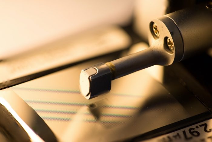
For many materials in the 21st century, a hardness test comprises of using a device that impacts the material with a defined amount of force over a specific amount of time before measuring the depth of the groove left behind. The commonly used hardness tests that measures the relationship between hardness and the depth of the indentation can be classified into the Rockwell, Brinell and Vickers hardness test.

Rockwell Hardness Test

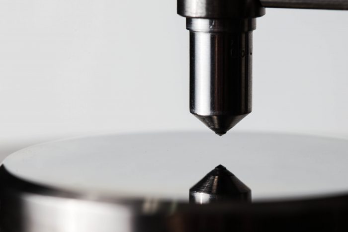
Rockwell hardness tests is one of the most commonly used hardness tests in the market due to its fast speed and high accuracy in determining the hardness of numerous materials such as metals, plastics and allows. When conducting this test, a hardened steel ball indenter or a diamond cone would be pushed into the material with a test force of 10kgf. Upon attaining equilibrium, more force would be used in order to cause a greater indentation depth. Once equilibrium is reached again, the force is removed, and the permanent depth of the indentation made would be used to determine the Rockwell hardness number of the material.

Additional Benefits Of Hardness Testing

By conducting a hardness test, the results obtained can be used to predict and determine the extent whereby the tested material can perform under various conditions. For example, by measuring the hardness at various temperature and humidity conditions can simulate and allow you to know if the hardness of the material would be impacted by storing it in a humid warehouse. If the hardness measurements remained constant, it indicates that the material can be stored normally. Otherwise, special precautions must then be taken to ensure proper storage of the material. Another instance would be testing the material’s hardness under prolonged exposure to various chemicals. This would allow you to determine the material’s resistance to chemicals and if special caution needs to be taken to ensure the functionality of the material is not affected by a chemical exposure.

Conclusion

All in all, a hardness test is a crucial test that you must adopt in ensuring that your product meets the stated quality specifications.

At Willrich Precision Instrument, we provide a large selection of hardness testers that would definitely meet the rigorous needs of your business! Browse through our exciting inventory and shop for quality surface roughness testers today. If you need assistance with any product purchase, call us at 866-945-5742 or email us at [email protected] today.

Understanding Bore Gages

A bore gage is an instrument that is frequently used to measure the internal of a hole. It is also known by many names such as bore mics, hole tests, holtests, internal micrometers or cylinder tests depending on your geographical region. It operates on the basis whereby parts known as the anvils expanding outward in order to determine its diameter when inserted into the hole. Read on to find out more about the characteristics and uses of bore gages.

Types Of Bore Gages

There are numerous types of bore gages in the market, with the more common types being bore gages with two or three anvils respectively. Bore gages with two anvils are cheaper and are calibrated with gauge blocks whereas those with three anvils are known as internal micrometers and are calibrated with setting rings. Both types can make use of either a digital or dial scale to display the measured diameter of the hole. Apart from the common bore gages, there are also more specific types specializing in various measurements, such as the dial bore gages, small hole gages and telescopic bore gages.

Sizes Of Bore Gages

Depending on the diameter of the hole that you are measuring, you would require different types of bore gauges that have various measurement sizes. If you are looking for a bore gage that can measure a wide range of sizes, an adjustable bore gage would be the equipment that is suited for your needs! However, this type of gage suffers from a lower tolerance in the measured diameter. If a high degree of accuracy is demanded in the final product, plug gages, which comes in fixed sizes would be the equipment that you have been looking for. Plug gages can be customized accordingly to your requirements, making them available in both small and large sizes.

Uses Of Bore Gages

With the high level of precision obtainable in a bore gage, there are many applications where it can be used such as the measurement of pipes, holes and cylinders, which are commonplace in the manufacturing, automotive and equipment calibration industries. Inspectors and maintenance staffs utilize bore gages to inspect the dimensions inside injection moldings to ensure that its quality are up to the desired standards, or in extruder barrels to monitor wear and tear over an extended period of time to find out when preventive maintenance can be carried out. Mechanics and machinists also make use of these equipment to detect the extent of wear and tear in cylinder heads and also to accurately measure holes in an engine block to ensure that the pistons fit tightly to prevent any gas leakages.

Conclusion

With the numerous potential applications of bore gages and its ease of customizability in terms of types and sizes, it serves as a handy tool that can greatly assist you in the measurement of a hole’s internal diameter.
At Willrich Precision Instrument, we provide a wide range of bore gages that would definitely meet the rigorous needs of your business! Browse through our exciting inventory and shop for quality bore gages today. If you need assistance with any product purchase, call us at 866-945-5742 or email us at [email protected] today.

Product Spotlight: Mitutoyo Linear Height LH-600E / EG Height Gage – 2D Measurement PROMO

Height gages are measuring devices designed to determine the height of a wide range of objects. One can use these devices to mark items that are being worked on. Today, height gage technology has gone through various stages of evolutions. These gages now have the ability to meet strict quality measurement demands of most precision laboratories. Regardless of where and how these gages are used, height gages have certainly stood the test of time and is an essential tool in every modern workshop.

If you are looking to get reliable height gages, you should consider getting our Mitutoyo Linear Height LH-600E / EG height gages. Mitutuyo’s products are recognized for their best-in-class accuracy. Their highly accurate guiding mechanisms and scale units are manufactured in Mitutoyo’s dedicated scale plant. Additionally, these gages have a measuring range of 0 – 38 / 0 – 972mm and a displacement accuracy of 1.7 μm (when measuring a height of 600mm). Do keep in mind that we are rolling out a limited time offer with the codes: PROMO 027 and PROMO 028. You can enjoy complimentary accredited calibration (a2la 0750.01) and other shipping benefits.

About Mitutoyo

Also known as Kabushiki Kaisha Mitsutoyo, Mitutoyo Corporation is a renowned Japanese MNC that designs and manufactures measuring instruments and other types of metrological technology. Founded in 1934 by Yehan Numata, the company is headquartered at Takatsu-ku, Kawasaki, Kanagawa. itutoyo started out by making high-quality and affordable micrometers for
manufacturing facilities. When it expanded over the next several decades, the company increased its product offering by focusing on mechanical, dimensional gaging products such as dial indicators, calipers, and other measuring tools.

In 1963, Mitutoyo America Corporation was formed and was headquartered in Aurora, Illinois. Located in close proximity to Chicago, this branch offered a full product line of precision measuring instruments, tools,
and equipment with a wider distribution network and even offered training
programs, service support, and software development services. The goal was to form a comprehensive metrology organization.

Features of Mitutoyo
Linear Height LH-600E / EG Height Gages

Here’s a quick look at some notable features of Mitutoyo Linear Height LH-600E / EG Height Gages:

  • Digimatic tool can be used for seamless data entry
  • Comes with a power grip
  • One-key operation while performing semi-automatic measurements
  • USB / RS-232C data output
  • Basic statistical function
  • Allows operator to adjust air-cushion height via semi-floating or pneumatic full system
  • Guaranteed straightness of 4μm
  • Guaranteed perpendicularity (frontal) of 5μm
  • Excellent accuracy

Get Mitutoyo Linear
Height LH-600E / EG Height Gages from Willrich Precision!

Willrich has been in business for over four decades and is
recognized for our unmatched products and services in the metrology, inspection, and gaging fields. If you are looking to get top-quality and reliable Mitutoyo height gages, we have everything you need in one place. You can enjoy complete peace of mind knowing that our company is ISO:9001:2008 Registered and can provide repair and calibration services. Whether you require height gages for military or medical applications, we have got your back with best in class products.

To know more about our Mitutoyo Linear Height LH-600E / EG height gages and the benefits they provide, do not hesitate to contact us today.

A Short Course On Measuring Pitch Diameters

Do you know that bolts, tapes, dies and other helically threaded components are characterized by various parameters? These parameters include depth, angle, pitch, major and minor diameters, whereby the pitch diameter holds the most significance amongst these parameters. Read on to find out more about the importance and the process of measuring pitch diameters!

What is a Pitch Diameter?

To many of us, the effective diameter, also known as the pitch diameter, refers to the diameter of the cylinder as it cuts the midpoint of both the major and minor diameters known as the pitch line. The pitch diameter is an important property that governs the compatibility between two threaded parts, such as nuts and bolts and if they can be successfully mated with each other. Moreover, they are also used as a crucial reference for other relevant thread measurements.

Measurement of Pitch Diameter

Due to the large susceptibility of pitch diameters to measurement errors, unique measuring equipment must be used in order to obtain an accurate reading. Although there exist many types of techniques to measure pitch diameter, there exist three most commonly utilized methods, namely the three-wire measurement method, the optical comparators and specialized micrometer screw gages which ensures the accuracy of your reading!

Three-Wire Method

The three-wire method makes use of a traditional, flat anvil micrometer screw gage to measure pitch diameter. Three separate wires of pre-measured diameter would be placed within the pitch of the threads before the gage of the wire is chosen. This enables the wires to stay in contact with the pitch line while simultaneously extending beyond the outside diameter of the thread. With another micrometer screw gage, the distance between the wires on the opposite sides are measured and used as inputs in prescribed formulas to derive the pitch diameter.

Optical Comparators

Optical comparators make use of the fundamental basis of optics and light to determine the pitch diameter. A magnified silhouette of the threaded object is projected on a screen and a specialized software would be used for image analysis and to obtain the pitch diameter. Through the use of optical comparators, it would result in a high degree of accuracy in pitch diameter measurements. However, a downside of it would be its expensive cost!

Specialized Micrometer Screw Gages

A commonly used instrument would be a form of micrometer screw gage known as a thread mic or a pitch mic. It was designed for the purpose of measuring the pitch diameters of cutting threading tools. To make use of this instrument, the ratchet of the micrometer is turned continuously until the spindle comes into contact with the thread flanks. The pitch diameter can then be read off from the micrometer scales. This method provides an efficient and accurate, but yet a low-cost way of measuring the pitch diameter!

At Willrich Precision Instrument, we provide a large selection of thread gages that would definitely meet the rigorous needs of your business! Browse through our exciting inventory and shop for quality thread gages today. If you need assistance with any product purchase, call us at 866-945-5742 or email us at [email protected] today.

A Guide To Measuring Surface Finishes

The finish, or surface texture of a finished component can be viewed differently from two different perspectives. For the designer, variations of surface texture would affect the functionality of the component. If the designer wishes to change the component’s functionality, the surface texture specification must be altered. From the machinist’s point of view, the finish is the end product of the manufacturing process and it can be altered by modifying the manufacturing process. Read on to find out more about measuring surface finishes and the various parameters involved!

Variations In Surface Finishes

Surface finishes contains the troughs and crests that comprises the surface and the direction of the surface. Through the usual machining processes such as grinding, milling and turning, uneven sections are being imparted onto the component’s surface. Moreover, other factors such as the vibration, speeds, condition of the machine tool and the choice of machine tool can also affect the extent of these irregularities. As a result, these factors must be carefully controlled.

Components Of Surface Finishes

Surface finishes can essentially be classified into 3 segments:

  • Roughness: Roughness stems from the usage of cutting tool that leaves a mark with a distinct depth and width. Also, in the cases of grinding, the abrasive granules on the wheel can also leave a groove on the surface of the component that is being produced.
  • Form: Form can be attributed to a lack of straightness or flatness in the machine’s cutting tool, resulting in the component’s surface finish being affected. This results in a systemic deviation from the specified requirements whenever the machine is being used.  
  • Waviness: Waviness of a component is defined as small variations in the length between the cutting tool and the produced component during the manufacturing process. These variations are caused by the instability of a cutting tool due to vibrations. The source of vibrations can be internal such as the motor of the machine or even externally induced due to the operations of other machines nearby. The waviness of the component can be measured by a contour measurement device.

How To Measure Surface Finishes

All of the above-mentioned surface finish components exist simultaneously and each condition is checked
separately. By measuring these components, the search for the origins of the error can be narrowed, allowing its effects to be reduced or eliminated. There are many instruments available in the market that would enable you to measure these 3 components, such as a pocket-sized, battery-powered gages. Its low price allows for the measurement of a small number of roughness parameters at an affordable cost. Furthermore, these instruments are also very flexible and are very easy to use. If you require more complex parameters to be measured, more precise equipment but expensive that involves powerful computers would be required!

At Willrich Precision Instrument, we provide a large selection of surface roughness testers and form measurement that would definitely meet the rigorous needs of your business! Browse through our exciting inventory and shop for quality surface roughness testers today. If you need assistance with any product purchase, call us at 866-945-5742 or email us at [email protected] today.

Product Spotlight: Mitutoyo Linear Height LH-600E / EG Height Gage – 2D Measurement PROMO

Height gages are measuring devices designed to determine the height of a wide range of objects. One can use these devices to mark items that are being worked on. Today, height gage technology has gone through various stages of evolutions. These gages now have the ability to meet strict quality measurement demands of most precision laboratories. Regardless of where and how these gages are used, height gages have certainly stood the test of time and is an essential tool in every modern workshop.

If you are looking to get reliable height gages, you should consider getting our Mitutoyo Linear Height LH-600E / EG height gages. Mitutuyo’s products are recognized for their best-in-class accuracy. Their highly accurate guiding mechanisms and scale units are manufactured in Mitutoyo’s dedicated scale plant. Additionally, these gages have a measuring range of 0 – 38 / 0 – 972mm and a displacement accuracy of 1.7 μm (when measuring a height of 600mm).

About Mitutoyo

Mitutoyo product offering by focuses on mechanical, dimensional gaging products such as dial indicators, calipers, Coordinate Measuring Machines and other measuring tools.

In 1963, Mitutoyo America Corporation was formed and was headquartered in Aurora, Illinois. Located in close proximity to Chicago, this branch offered a full product line of precision measuring instruments, tools, and equipment with a wider distribution network and even offered training programs, service support, and software development services. The goal was to form a comprehensive metrology organization.

Features of Mitutoyo Linear Height LH-600E / EG Height Gages

Here’s a quick look at some notable features of Mitutoyo Linear Height LH-600E / EG

  • Height Gages
  • Digimatic tool can be used for seamless data entry
  • Comes with a power grip
  • One-key operation while performing semi-automatic measurements
  • USB / RS-232C data output
  • Basic statistical function
  • Allows operator to adjust air-cushion height via semi-floating or pneumatic full system
  • Guaranteed straightness of 4microns
  • Guaranteed perpendicularity (frontal) of 5microns
  • Excellent accuracy

Get Mitutoyo Linear Height LH-600E / EG Height Gages from Willrich Precision!

Willrich has been in business for over four decades and is recognized for our unmatched products and services in the metrology, inspection, and gaging fields. If you are looking to get top-quality and reliable Mitutoyo height gages, we have everything you need in one place. You can enjoy complete peace of mind knowing that our company is ISO:9001:2008 Registered and can provide repair and calibration services. Whether you require height gages for military or medical applications, we have got your back with best in class products. Willrich has been in business for over four decades and is recognized for our unmatched products and services in the metrology, inspection, and gaging fields. If you are looking to get top-quality and reliable Mitutoyo height gages, we have everything you need in one place. You can enjoy complete peace of mind knowing that our company is ISO:9001:2008 Registered and can provide repair and calibration services. Whether you require height gages for military or medical applications, we have got your back with best in class products.

To know more about our Mitutoyo Linear Height LH-600E / EG height gages and the benefits they provide, do not hesitate to contact us today

Understanding The Role Of Force Measurement In Linear Drives

force measurement

Force is defined as an interaction that has the ability to change the direction of an object. This, however, is only on the condition that the process is unopposed. Force is capable of making any object with mass to alter its velocity and this also includes objects that were initially at rest. Force takes many forms but is inherently either pull or push action applied onto an object. Force tends to have magnitude (how much of the force is being applied on the object) and it also has direction. For this reason, force always has a vector unit. When looking at force, there are certain concepts that one needs to understand.

Key Terms to Understand

There are a number of concepts that are common when talking about force. Thrust refers to the process of increasing the velocity of an object. There is also drag which counters the effect of thrust and decreases the velocity of an object. Another common term that is used when discussing force is known as torque which affects the rotational speed of the object in question. Another term that is common in this field is static. This refers to the description of objects that are at rest. In such cases, there is zero force acting on the object. Static can also happen when there are two opposing forces of equal magnitude acting on the object.

How is Force Measured?

There are various technologies that are used to measure force. These include Thin-film technology where a sputter process is utilized to achieve an atomic bond between the measuring bridge and the measuring cell body. This process is very ideal for measuring force in highly automated processes. Another common approach is to use a strain gauge where a resistance meander is attached to a strip of foil and this is then attached to the point where force is being applied.

Linear Drives

Linear drives are systems that cause translational movement. Because machine elements accelerate in a straight line, it’s logical to have force measurement in those drives as transformational change is taking place. Drive elements have traditionally been driven by hydraulics or are pneumatically powered. This is increasingly changing, and these kinds of drives are being replaced by electric motors, mechanical thrust units or a combination of both. Although these modern systems work through modular systems, they can be adapted to specifically match the needs of the user. The modern systems also have a greater degree of versatility. The only drawback of these systems is that you can no longer measure the pressure of the system.

Advantages of Force Measurements

Force measurement can be done with any linear drive. When you are looking to make precise force measurements, you can place the force transducer anywhere within the system. This will not affect the accuracy of the measurements that you take. Whether you place the force transducer on the actuator, the motor or the precise point where the force is being applied, you are still likely to get the right results.

Top Tips To Facilitate Rockwell Hardness Tests

hardness test

Hardness is defined as the measure of resistance that a material has when force is applied to it. Others may refer to hardness as the ability of a substance to resist scratching, cutting or abrasions. There is a direct relationship between the level of hardness of an object and the level of its resistance. The greater the hardness, the greater the resistance. Hardness is largely determined by a substance’s microstructure. Hardness matters because it gives us an indication of how the material will stand up against pressure. This has implications on how the material can be used and what kind of pressure it can withstand. For this reason, measuring hardness is a routine procedure in most quality control processes. Here are some of the ways of facilitating Rockwell hardness tests.

Check Indenter

Before carrying out a Rockwell hardness test, it is critical to ensure that there is no chipped or cracked diamonds on the indenter. This is because any of such anomalies are likely to lead to errors in the readings. Experts recommend checking the indenter every week with a magnifying device (such as a Jeweler’s eye loop). However, it might be hard to tell if the indenter is damaged. For this reason, if you notice consistent erroneous readings, this might be another clue that there is a problem with the indenter.

Verify Hardness Readings

Before performing a test, experts recommend that you test the hardness of a test block. This is a block with a hardness that is already known and thus the idea is to check if the reading from the tool is consistent with the known hardness. It is usually standard to do at least three tests in order to establish a consistent reading. It is also standard to discard the first reading after an indenter or an anvil change.

Keep the Rockwell Hardness Tester Clean

Debris, dirt and other contaminants can affect readings. It is important to remove and clean the indenter and anvil before you start testing. It is also critical to do this at every break between the shifts so that all parts of the tester stay clean throughout the day.

 Smoothen Surfaces

When testing objects that are rough or that have textured surfaces, it is important to be aware that these kinds of surfaces can affect the readings obtained from the tester. To help overcome these kinds of problems, ensure that you lightly sand the surface to reduce the roughness.

Watch out For Movement

If you get any movement of the part while doing a test, you should discard the reading and perform another test. You should also avoid including these readings in your final average. This is because the movement of the part can affect the accuracy of the test.

Watch out for the Edge

When you take readings very close to the edge, it might cause problems with the reading and might even damage the indenter. Ensure that all readings are made at least 2.5 times the diameter of the indenter from the edge. The key to note is that if the metal buckles outward, then you have positioned the indenter too close to the edge.

Product Spotlight: Fowler Trimos V7 Electronic 2D Height Gage

height gage

Height gages have been in use for many decades to measure heights of objects. Height gage can also be used to measure a variety of other parameters. These include diameters, radii, and more. Over the years, height gages have evolved and today, we have digital height gages where a lot of the processes are automated. This makes it easier for machinists to use height gages.

One such height gage is the Fowler Trimos V7 Electronic 2D Height Gage. This is an easy-to-use height gage that comes with a modern touch screen. It comes with a lateral insert holder that makes it great for use in a workshop. In order to improve clarity, the touch screen is very simplified so that the machine operator will not get distracted by clutter. In continuance with the drive to simplify things, the number of buttons is limited to only what is absolutely necessary.

The advantage of this is that operating the machine becomes very simple so one can easily perform complex operations simultaneously. The other advantage is that not a lot of training is required to get new workers to operate the machine. This saves a lot of time and costs, ensuring that productivity is always at its maximum.

About Fowler High Precision

Fowler High Precision Company is widely recognized as one of the leading manufacturers of precision equipment in the world. The company was founded in 1946 and since then, it has grown to where it is today. Fowler High Precision has managed to remain dynamic thanks to strategic partnerships with other companies such as Wyler and Trimos among others. This way, Fowler has ensured that they remain at the peak of the technology curve. This is reflected in the state-of-the-art products that the company supplies such as the Fowler Trimos V7 Electronic 2D Height Gage.

Features of Fowler Trimos V7 Electronic 2D Height Gage

Here’s a quick look at some notable features of Fowler Trimos V7 Electronic 2D Height Gage:

  • 2D programming, statistics
  • Large range of accessories
  • Measuring ranges 400 to 1800mm
  • Manual or motorized displacement
  • All possible adjustments without tools
  • Interfaces RS232 and USB
  • Simple and easy-to-use graphic interface
  • Electronically adjustable measuring force

 Get Fowler Trimos V7 Electronic 2D Height Gage from Willrich Precision!

Willrich Precision is your go-to supplier of top-quality precision instruments such as the Fowler Trimos V7 Electronic 2D Height Gage. We have been serving numerous customers for over 50 years and we have established a reputation as a trusted business partner. Our unique business model focuses on providing solutions to our clients. This is why we go out of our way to offer advice and assistance to clients who are not sure what instruments work best for their needs. 

When you come to Willrich Precision, you can have peace of mind that you are getting top quality precision instruments at very competitive prices.

To know more about our Fowler Trimos V7 Electronic 2D Height Gages and the benefits they provide, do not hesitate to contact us today.

Non-Destructive Precision Measurement Methods

measurement methods

In machining shops and quality control processes, it is a routine for quality control personnel to measure a variety of items in order to have consistency in what is being produced.  When conducting such processes, you have the option to use measurement methods that do not cause any damage to the part, work area or the system. These are the methods that we are describing as non-destructive methods and they are widely used in a variety of applications.

Thickness Gage

This is a gage that is used to measure the thickness of load-bearing structures and more. Thickness gages use sound to measure the thickness of a substance. It does this by sending an ultrasonic sound wave through the object. The thickness of the object is measured by the time it takes for the sound to get through to the part and back. Obviously, the thicker the object is, the longer it takes for sound to travel through to the part. The beauty of using the thickness gage is that there is little to no contact with the part being measured and this reduces the possibility of damage to the part.

Thermal Imagers

Thermal Imaging is a form of non-contact measurement that works by detecting infrared energy that is emitted by all substances. The imager then transforms the energy into a temperature reading. The thermal imaging process is great at discovering problems in substances that are harder to assess in any other way. For example, thermal imagers are excellent at evaluating moving objects, hazardous materials and in all other cases where there is a risk of damaging the substance being measured.

Flaw Detectors

Flaw detectors are used to look at flaws in a variety of objects. For example, flaw detectors can spot cracks in a cavity or a wall. This is particularly useful because it saves you the trouble of opening up the cavity itself to check for flaws. Flaw detectors also use ultrasonic waves (sound) to detect flaws in structures and substances. Being able to detect flaws is critical because the failure of a part or a structure is often preceded by internal flaws that can’t be seen externally.  

Hardness Testers

There are many reasons to test for hardness. In most cases, the hardness of an object gives an indication of how well it will withstand pressure. Applications for this are found in the motor vehicle industry and many others. Hardness testers only minimally affect the part that is being tested and this is why they are classified as non-destructive precision instruments. When using a hardness tester, a specifically dimensioned tool is pressed into the part and reading is done by measuring the depth that the indenter returns.

Voltage Sensors

With a voltage sensor, one can measure the level of current passing through a particular material. When machinists and quality control personnel are doing this, they are trying to prevent the object that is under study from being damaged by electric current. If a substance is not supposed to conduct electricity but still does anyway, it might cause harm to the person using the object.

How To Improve Bad Boring Performance

boring performance

There are several factors that can affect boring performance. These factors include short tool life, bore quality and much more. In order to improve bore performance, a machinist must start by fixing any of these things in case there is a problem with them. When you are trying to fix bad bore performance, it is critical that the machine operator changes various parameters and do a test so that he or she can isolate what is wrong with the bore performance.

Part Instability

This is often overlooked as most machinists tend to assume that the problem must be with the bore. The truth is, on many occasions, part instability has a big role to play in most cases of poor boring quality. When the machine has worn spindles, there is the risk that this will affect boring quality. Fortunately for a machinist facing this kind of problem, the solution is usually simple and involves changing cutting parameters as well as insert types.

Check Stock Allowance

Machinists struggle with figuring how much stock to leave for boring applications.  When boring, the machinist must remember that parts with reduced stock allowance work best with boring tools with a single point cutter. If you only have a twin cutter bore, the machinist can get around this problem by removing one of its insert holders.

Select Tools for the True Bore Depth

Machinists often choose boring tools based on the target bore gage and diameter. However, most don’t think of the actual bore depth. When you need extra tool length, the machinist can initially have a larger base and then decrease the tool diameter. This yields better results than using the same bar diameter across the length of the tool.

Machine Inserts

Inserts are critical as they lie between the tool and the part that is being worked on. Inserts determine the quality of the boring and can affect it regardless of how good the boring assembly is. Inserts, on the other hand, are affected by the geometry and in this case, pressed geometry is able to withstand stable conditions. The good news for machinists is that inserts are always being improved to optimize their performance during boring operations. However, regardless of the quality of the inserts, the ultimate determiner of the life of an insert is the stability of the cuts that are made with it. 

Speed

This refers to the speed and feeds that are used to run the boring system. Machinists must always consider the surface of the part that they are boring. For example, when roughing, the machinist can use more rigid bore toolsbecause the surfaces do not need fine surface finishing. Speed also affects the life span of the inserts. If the machine is run at a very high speed while making heavy cuts, there is a chance for the excessive heat to reduce the life of the inserts.

Handling these factors well will help you achieve better boring performances and protect your boring system as well.

Product Spotlight: Fowler Trimos V7 Electronic 2D Height Gage

Height gages have
been in use for many decades to measure heights of objects. Height gage can
also be used to measure a variety of other parameters. These include diameters,
radii, and more. Over the years, height gages have evolved and today, we have
digital height gages where a lot of the processes are automated. This makes it
easier for machinists to use height gages.

One such height gage is the Fowler Trimos V7 Electronic 2D Height Gage. This is an easy-to-use height gage that comes with a modern touch screen. It comes with a lateral insert holder that makes it great for use in a workshop. In order to improve clarity, the touch screen is very simplified so that the machine operator will not get distracted by clutter. In continuance with the drive to simplify things, the number of buttons is limited to only what is absolutely necessary.

The advantage of
this is that operating the machine becomes very simple so one can easily
perform complex operations simultaneously. The other advantage is that not a
lot of training is required to get new workers to operate the machine. This
saves a lot of time and costs, ensuring that productivity is always at its
maximum.

About Fowler High Precision

Fowler High
Precision Company is widely recognized as one of the leading manufacturers of precision
equipment in the world. The company was founded in 1946 and since then, it has
grown to where it is today. Fowler High Precision has managed to remain dynamic
thanks to strategic partnerships with other companies such as Wyler and Trimos
among others. This way, Fowler has ensured that they remain at the peak of the
technology curve. This is reflected in the state-of-the-art products that the
company supplies such as the Fowler Trimos V7 Electronic 2D Height Gage.

Features of Fowler Trimos V7 Electronic 2D Height Gage

Here’s a quick look
at some notable features of Fowler Trimos V7 Electronic
2D Height Gage:

  • 2D programming,
    statistics
  • Large range of
    accessories
  • Measuring ranges 400
    to 1800mm
  • Manual or motorized
    displacement
  • All possible
    adjustments without tools
  • Interfaces RS232 and
    USB
  • Simple and
    easy-to-use graphic interface
  • Electronically
    adjustable measuring force

 Get Fowler
Trimos V7 Electronic 2D Height Gage from Willrich Precision!

Willrich Precision
is your go-to supplier of top-quality precision instruments such as the Fowler
Trimos V7 Electronic 2D Height Gage. We have been serving numerous customers
for over 50 years and we have established a reputation as a trusted business
partner. Our unique business model focuses on providing solutions to our
clients. This is why we go out of our way to offer advice and assistance to
clients who are not sure what instruments work best for their needs.

When you come to Willrich Precision, you can have peace of mind that you are getting top quality precision instruments at very competitive prices.

To know more about
our Fowler Trimos V7 Electronic 2D Height Gages and the benefits they provide,
do not hesitate to contact us today.

Top Tips To Facilitate Rockwell Hardness Tests

Hardness is defined as the measure of resistance that a material has when force is applied to it. Others may refer to hardness as the ability of a substance to resist scratching, cutting or abrasions. There is a direct relationship between the level of hardness of an object and the level of its resistance. The greater the hardness, the greater the resistance. Hardness is largely determined by a substance’s microstructure. Hardness matters because it gives us an indication of how the material will stand up against pressure. This has implications on how the material can be used and what kind of pressure it can withstand. For this reason, measuring hardness is a routine procedure in most quality control processes. Here are some of the ways of facilitating Rockwell hardness tests.

Check Indenter

Before carrying out a Rockwell hardness test, it is critical to ensure that there is no chipped or cracked diamonds on the indenter. This is because any of such anomalies are likely to lead to errors in the readings. Experts recommend checking the indenter every week with a magnifying device (such as a Jeweler’s eye loop). However, it might be hard to tell if the indenter is damaged. For this reason, if you notice consistent erroneous readings, this might be another clue that there is a problem with the indenter.

Verify Hardness Readings

Before performing a test, experts recommend
that you test the hardness of a test block. This is a block with a hardness
that is already known and thus the idea is to check if the reading from the
tool is consistent with the known hardness. It is usually standard to do at
least three tests in order to establish a consistent reading. It is also
standard to discard the first reading after an indenter or an anvil change.

Keep the Rockwell Hardness Tester Clean

Debris, dirt and other contaminants can affect
readings. It is important to remove and clean the indenter and anvil before you
start testing. It is also critical to do this at every break between the shifts
so that all parts of the tester stay clean throughout the day.

 Smoothen
Surfaces

When testing objects that are rough or that
have textured surfaces, it is important to be aware that these kinds of
surfaces can affect the readings obtained from the tester. To help overcome
these kinds of problems, ensure that you lightly sand the surface to reduce the
roughness.

Watch out For Movement

If you get any movement of the part while
doing a test, you should discard the reading and perform another test. You
should also avoid including these readings in your final average. This is
because the movement of the part can affect the accuracy of the test.

Watch out for the Edge

When you take readings very close to the edge,
it might cause problems with the reading and might even damage the indenter.
Ensure that all readings are made at least 2.5 times the diameter of the
indenter from the edge. The key to note is that if the metal buckles outward,
then you have positioned the indenter too close to the edge.

Understanding Ra Values for Product Development

Ra values

Surface roughness is also known as Ra, but not many people understand what Ra values implies, how it is measured, and why it is critical to product design. Here is what you need to know about Ra values.

Understanding Ra Values

If you take a sample of a part and measure the high and low points of its length, Ra is the mean or average height that lies above or below the line of reference. The higher the Ra number, the rougher a surface is. If Ra is 0, the graph will show a horizontal line, which means the surface is flat. This is impossible.

Other measurement systems operate on the same principle but are not precisely similar. This can cause errors and confusion, so it is essential to know which method you are referring to and to ensure it is identical to that of your part manufacturer. Always ask if you are not sure as conversion charts are available for system-to-system translation if required.

How the Ra Value Concerns You

The Rvalue is the industry standard for giving instructions to a manufacturer on what the roughness level should and should not be for you. This is used for tooling, machined parts and prototypes. It also affects the part’s appearance, functionality as well as its performance.

Ra shows the average mean deviation or the highest high or low, calculated over the sample’s length. There are many ways to achieve the same mean by using various manufacturing processes. All of which will leave a distinctive pattern on the surface. Manufacturers utilize gages to measure and make comparisons on how different machining methods produce differing types of textures.

The patterns on the gauge surfaces differ in the groove spacing, also known as waves. It is one of the factors that determine surface texture. The waves found on the left are of a low frequency, and the frequency increases from left to right. The R, average height, may be similar but the appearance is not.

How Surface Texture is Measured

Surface texture can be measured with different methods, depending on the part geometry, material type, and part feature. A common technique is to use a stylus or probe, also called a surfometer. It is slowly drawn over the part’s face or feature. Any deviation from a reference line is recorded as a gap to be interpreted later.

The Ra value is calculated with ease via such a reading. It may be more desirable to look at the surface area from a broader view to check for more defects on the surface. This can be done via optical photometry.

One primary utilization of optical photometry to identify asperities. These may be scratches, contaminants in the raw material or voids. Mathematically obtained models tend to consider these irregularities as non-important, but for essential applications in defense, scientific and aerospace instruments, an anomaly would be disastrous.

It takes a combination of both machine and human intelligence for the right decision on surface texture to be made.

Product Spotlight: Brown & Sharpe TESA MICRO-HITE +M Motorized Height Gage

Brown & Sharpe TESA MICRO-HITE +M Motorized Height Gage

Height gages are versatile and useful equipment that allow machine operators to measure the height of any part or object. Height gages have other applications as well. For example, Brown & Sharpe TESA MICRO-HITE +M Motorized Height Gage allows you to easily measure the diameter and radius of a part. Height gages have evolved over the years and the modern digital ones have a lot more to offer and are easy to use. 

A good example of such a gage is the Brown & Sharpe TESA MICRO-HITE +M Motorized height gage. This easy-to-use gage features an interactive LC display and allows the user to toggle between motorized and manual operation. This amazing instrument from Brown & Sharpe also has a built-in air cushion and can be programmed to automatically run measurements for its most routine and common functions. This saves the operator valuable time as it eliminates the need for constant set-up.

About Brown & Sharpe

Brown & Sharpe is a well-known manufacturer of metrological tools and has been in operation since 1893. The company is now part of the Hexagon AB Group, a Swedish company that acquired Brown & Sharpe in 2001. For most of the 19th and 20th centuries, Brown & Sharpe was regarded as the leading producer of instruments for machinists. Brown & Sharpe has been setting standards for the industry for many years and all its instruments are ranked among the best. This includes the Brown & Sharpe TESA MICRO-HITE +M Motorized height gage which comes with a host of advanced features which we will talk about below.

Features of Brown & Sharpe TESA MICRO-HITE +M Motorized Height Gage

Here is a quick look at some of the top features of the Brown & Sharpe TESA MICRO-HITE +M Motorized Height Gage:

  • Adjustable hybrid multi-user panel 
  • 2D-measurement due to clear graphic visualization
  • Context-based help – intelligent user follow-up
  • Adjustable Panel
  • Standard and advanced 1D& 2D measuring
  • Motorized Height Gage
  • Fast measurements thanks to one-of-a-kind rotary measuring control
  • The choice between 2 intuitive control panels
  • Coefficient of linear expansion comparable to that of steel

Get Brown & Sharpe TESA MICRO-HITE +M Motorized Height Gage from Willrich Precision!

At Willrich, you can be sure that we will supply you with the best in height gages including the Brown & Sharpe TESA MICRO-HITE +M Motorized height gage. We have nearly 5 decades of experience and have many happy customers who rely on us for all their precision instrument needs. Our staff members are happy to share with you any information you may require regarding our products and will even help you select the right instrument for your needs. You can call, email or use the chat function on our website to talk to any of our experts.If you wish to know more about Brown & Sharpe TESA MICRO-HITE +M Motorized height gage, do not hesitate to talk to a Willrich specialist today!