Understanding The Use of Equator Gauging Systems In EV Production

Equator gauging systems EV production

Equator gauging systems are specifically
designed for the needs of production lines. They make it possible for
production engineers to perform high-speed measurements accurately and with
much more flexibility than standard gauges can allow. The systems can be
tailored to meet the specific needs of a particular production line complete
with accessory options for manual and automated production lines.

The system works by comparing a pre-set master with the parts that are being measured. Equator gauging systems are also able to compensate for thermal conditions in the shop floor, making readings far more accurate. The gauges also come re-zeroed which eliminates the need to configure them before they can be used. These properties have made these gauges popular in many industrial processes and more so the production of electric vehicles or EVs. Here is how these gauges are transforming the production of EVs.

Equator
Gauges in EV Production

Any
car production system requires the fast and accurate measurement of hundreds of
parts and pieces. The accuracy of this gaging process plays a role in the
safety and reliability of the cars that come out of that proves. This is where
the equator gauging system has really made a difference in the production
lines. These gauges have been so effective that thousands of them are in use in
EV production lines across the United States, Europe, and Asian markets. The
system has worked especially well with the MODUS programming software that allows
for customization of the gaging process to suit the needs of any production
line.

Complete
Control

Using the
equator gauging system, production engineers have complete control over the
production process. To make it more powerful, the gaging system is compatible
with the Intelligent Process Control (IPC) software that enables the automatic
monitoring and adjustment of all machining processes in a production line. By
making this process automatic, production speed is significantly improved while
variances from the set master are minimized considerably. This, in turn,
reduces wastage and significantly increases revenue.

Manual
Vs. Automated Gaging
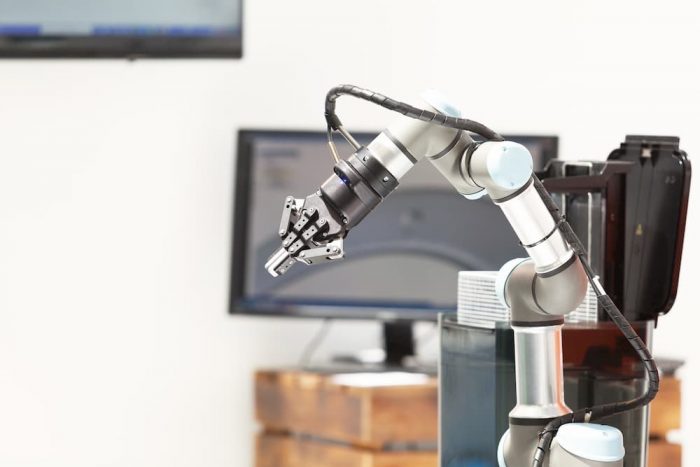
Another
advantage of equator gauging systems is that they can be customized to work
with the same application demands of other gaging systems. As EV production
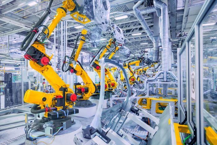
becomes more and more automated, the equator gauging system comes with the
ability to work in automated systems which include robotic machines and
conveyors. What this means is that the system can work with existing systems
but is also ready for the future of automotive production systems. The system
can also be customized to work in harsh environments. In such a case, the equator
gauging system is installed in an enclosure that protects the system. Parts can
then be loaded and removed without interfering with the system.

Willrich Precision Instruments is your seller of choice for a wide range of precision measuring instruments for the last forty-five years and we back all our products with excellent support and warranties.

What Is The Proper Way To Read Height Gages?

Read height gages

Height gages allow a machine operator to measure the depth of an object with pin-point accuracy. These gages differ immensely from model to model but most have the same basic structure. They consist of an arm that is usually in contact with the object being measured and a measuring unit that moves up and down the scale. Height gages typically measure vertical spaces but can also measure other dimensions such as internal and external diameters. Ever wondered about the proper way to read height gages? Read on to find out more:

Vernier Height Gages

The
first step when using this kind of height gage is to lock the arm into position
after placing it at the top of the object being measured. When this is done,
you need to then find the ‘zero” on the vernier scale that goes along with the
moving part on the scale. Look at the number on the upright shaft that falls
across the zero marking. Take note of this number as it is the first portion of
your measurement. When this is done, look at the numbered line on the vertical
scale that best aligns with a line on the vertical shaft. This number becomes
your final portion of measurement. The final step is to combine the zero
measurements with the best-aligned measurement to get the final height
measurement of the object you are measuring.

Dial Height Gages

Start
with positioning that arm in place at the top of the object that you want to
measure. When this is done, take note of the last number located beneath the
measuring equipment on the shaft. These numbers are likely to be in increments
of 0.1 inches. Take note of the number that the needle is indicating on the
dial face. The final step is to combine the measurement that you took on the
vertical shaft with the measurement that you noted from the dial face. The
combined number that you get represents that height of the object that you are
measuring.

Digital Height Gages

When taking measurements using this type of height gage, place the arm in position at the top of the object that you wish to measure. When this is done, find the digital display on the height gage and take note of the number that is shown on the display. This number is the height of the object that you are measuring. With digital height gages, you do not have to take the ‘zero’ setting as this is automatically set by the gage when you switch it on. For this reason, digital height gages are very popular as they can give readings much faster than the other two. This ability is critical in a manufacturing process where the quality control officers have to randomly test samples from the production line without slowing down the production process.

Looking
for high-quality height gages? Willrich Precision Instruments has been
providing clients with the best precision instruments for over four decades. We
are a one-stop-shop for all your precision instrument needs.

Understanding the Use of Air Gaging in The Automotive Industry

Air-gages

Air gaging is the use of compressed air to measure small spaces and hard to reach areas. Air gaging works by forcing a stream of air through finely tuned nozzles. The air gage then measures various dimensions of the space based on the air backstream. Air gages have over the years become hugely popular due to their flexibility and ease of use. Air gages have been used in the automotive industry for many years. Here are some of the ways that these useful gages serve the automotive industry.

Measuring Connecting Rods

Connecting rods are rigid components of the engine that link a piston to a crankshaft. By doing this, the connecting rods help to transform reciprocating motion into rotating motion or vice versa. Connecting rods are found in many types of engines but the most popular use is in automobile engines. Connecting rods require a very high degree of precision for them to function adequately. If one of the connecting rods fails, it often results to complete engine failure.

Use of Air Gages

During the manufacturing process, air gages are used to measure the distances between the piston end of the connecting rods and the crank end bores. Care is taken to ensure that the diameter, flatness of the parting surface and many other elements of the connecting rods are standardized and are up to the required dimensions. This is because any error in these elements can cause the engine to perform at less than its optimal level.

Air jets are used because they are insensitive to the diametrical size as well as to rod movement. This way, any variability associated with operator technique is eliminated. Accurate measurements can be taken fast and easily. This is especially useful in a factory setting where these parts are typically produced in their thousands every day and quality control operators need to measure random samples fast and accurately.

Workbench Version

The bend and twist gage have a bench version. This particular gage is good for busy workshops with a high volume of inspections. The device has a bend and twist fixture and also has an air to electric converter. The design of the gage is configured for easy and fast loading of workpieces. The data is also captured on the user interface and can easily be transferred on to a computer or another type of platform for analysis and storage

No Wear and Tear

One other reason why air gage is popular in the automotive industry is the fact that they are not susceptible to wear and tear. This is unlike contact gages such as calipers which come into contact with the part being measures. Air gages also clean the surface that is being worked on, meaning that dust and other elements do not affect the integrity of the readings from the air gage.

In conclusion, air gages are a bedrock of the automotive industry. As we have seen, they offer a flexible and fast way to measure samples.

There’s More Than One Approach Toward Air Gaging

air gaging

Air gaging was first developed as a technique to measure automotive parts. The gage worked by sending a stream of air into a bore and comparing the resulting airflow to a fixed amount of airflow. Air gaging has changed over the years, but the principle remains the same. Modern air gages measure the backpressure while the old gages were known as flow gages. Modern approaches to air gaging take different forms. Here are some of the commonly used methods.

Back Pressure Bleed System

This is a versatile form of air gaging where the air gage has an air regulator to control incoming air pressure. The gage also has a second restriction where the operator can adjust for various air gage tooling and readouts. This is done by adjusting the air pressure to match the kind of tooling being applied at the moment. This system also has its magnification controlled by the restriction between the regulator and the air gage. The second restriction serves to calibrate the tool and helps to establish the tolerance range of the tool.

The advantage of the bleed system is that it allows this air gage to operate at higher pressures than most other systems. These air gages also last much longer than most other systems because the nozzles are situated further away from the measuring surface thus reduced wear and tear.

Back Pressure System

This is simply a variation of the bleed system without the second restriction. This lack of a second restriction severely limits the applications of this air gage. For accurate readings, this air gage requires tooling and amplifies with restricted ranges. For this reason, many manufacturing processes do not use this kind of air gage.

Differential System

This type of air gaging is also known as a balanced system where the air is split into two and moves through these two channels. One end has a zero valve which is used to balance the pressure on the second airflow which terminates at the air plug.  A differential pressure meter measures the difference between these two legs and the gage is usually set to zero. One of the drawbacks to this kind of tooling is that the single-master system has a fixed magnification. This means that any bad or worn-out tooling must be taken back to the manufacturer as this would have an adverse effect on the readings being taken by the tool. This kind of air gaging also has each amplifies accommodating only one full-scale value. For that reason, different tolerances require several amplifiers.

Flow System

As discussed, these were among the original air gage and worked by measuring the airflow variation in a tube which holds a float. Flow systems are fairly accurate as they work with a two-master system and the range of magnification can be adjusted by changing flow tubes. Flow gages require a larger amount of air and nozzle sizes generally vary from brand to brand.

Product Spotlight: Brown & Sharpe Tesa Micro-Hite 350/600/900

Brown & Sharpe Tesa Micro-Hite 350/600/900

Both traditional and digital height gages are important tools in the world of precision measurement and metrology. While it is sometimes viewed as a giant caliper, this sophisticated benchtop gaging system has the ability to perform measuring tasks reliably and quickly. If you are looking to get a versatile height gage like the Brown & Sharpe Tesa Micro-Hite 350/600/900, you have come to the right place. This product (available at Willrich Precision) allows users to accurately measure deviations from perpendicularity, straightness, and length. With RS 232 data output and an interactive display, your jobs will be so much easier from now on. 

About Brown & Sharpe

It is a well-known and influential machine tool builder that was founded in 1833. It is considered the leading manufacturer of instruments (e.g., indicators and micrometers) for machinists worldwide. Since its inception, the renowned brand has also help established several industrial standards: worm threadform standards for worm gears; taper standards in machine tool spindle tapers; and the American wire gauge standards (AWG).

In 2001, Brown & Sharpe merged with TESA Technology, which is the premier Swiss manufacturer of precision measuring instruments. TESA is also part of Hexagon Manufacturing Intelligence (one of the world’s largest metrology product provider). The latter has a solid track record of developing today’s disruptive technologies and life-changing products of the future. Today, Hexagon Manufacturing Intelligence continues to build products that give industrial manufacturers the confidence to accelerate productivity while retaining product quality as easily as possible. 

Features of Brown & Sharpe Tesa Micro-Hite 350/600/900

Here is a quick look at some of the top features of Brown & Sharpe Tesa Micro-Hite 350/600/900:

  • Takes both 1D and 2D measurements
  • Full-color touchscreen
  • Adjustable panel
  • Comes with and without fine adjust devices
  • Air cushioning feature
  • Manual operation
  • Clear graphic visualization (great for 2D measurements)
  • Can be connected with printer
  • Easy data transfer to USB stick
  • Generates PDF measurement reports directly from the program
  • Context-based assistance
  • LED control lighting (needed for efficient determination of culmination points)
  • Adjustable hybrid multi-user panel
  • Covered under four-year warranty plan

Get Brown & Sharpe Tesa Micro-Hite 350/600/900 from Willrich Precision!

Willrich Precision is a trusted provider of top-quality height gages, including the Brown & Sharpe Tesa Micro-Hite height gages. Our company has been in business for more than 40 years and have vast experience in the fields of metrology, gaging, and inspection. When you shop at Willrich Precision, enjoy complete peace of mind that all of our products are competitively priced. In addition to affordability, each height gage purchase comes with a SCS calibration certificate. 

Since our inception, Willrich Precision has been providing reliable height gages for firms in the aerospace, medical, plastics, pharmaceutical, technology, energy, automotive, military, and firearms industries. Regardless of which precision measuring challenges that are causing roadblocks, our knowledgeable sales representatives can help you find the perfect solution. If you wish to know more about Brown & Sharpe Tesa Micro-Hite 350/600/900, do not hesitate to talk to a Willrich specialist today!

How to Make the Most Out of Your Height Gages

height gages

Height gages are used to measure a lot more than just heights. These useful measuring tools trace their origins back to the 16th century when Pierre Vernier developed the vernier scale. This scale allowed mathematicians and engineers to measure accurately. So good was his system that the scale became the standard of quality measurements for the next four centuries. From this, the vernier height gage and the gear tooth vernier height gage were developed and became widely used throughout various industries.

The height gage as since come a long way and a lot of other useful functionalities have been added to it. Its basic design has not changed much though. It looks like a hand-held caliper that rests on a heavy base that keeps the tool aligned to the surface. In the original machines, the scale had a movable jaw that was used to mark a part to indicate a measurement. Here is how to get the most out of your height gage.

Setting it Up

Before you can use your height gage, you will need to set two references. The first of those is the zero-reference which the tool is able to set automatically. It does so by moving to touch the surface to set a reference point. Machining experts recommend that you do this process twice so as to ensure that no dirt or other anomalies interfere with the reference.  The other point of reference is correcting for probe ball diameter. This reference does not matter very much if the gage is only being used to measure heights. 

If, however, the gage will be used to measure grooves or diameters, then it is important to take the probe ball diameter into account. For most modern height gages, the probe ball diameter is measured automatically and its dimensions automatically factored into all readings. The machine takes a fixture that comes with the gage which sets up a plane. This plane is measured from the two opposing directions and the difference between the two measurements is taken as the ball diameter.

How to Measure

Modern digital height gages make it easy to take any measurement. All the operator needs to do is to slide the measuring carriage across the part that is being measured and press a button. The gage will move the carriage from the top to the surface and print out the height reading on the display. Modern height gages allow the operator to manipulate and share data. They come with data ports and other useful connectivity options that allow for the transfer of data to computers and other platforms for analysis and storage.

Things to Look Out For

One of the most common sources of bad readings from height gages is when an operator takes higher than recommended height measurements without changing the base. When this happens, the gage wobbles (although this may not be discernable) and this influences the measurement.

Air Gaging Is An Accurate Way To Measure Physical Qualities

Air Gaging

Are you new to the term: air gaging? Firstly, you will need to know how gage is defined. It is basically a tool and service used to measure a physical quality. This means that the gage can be used in any scheme of quantity production interchangeably. In addition to measuring the contents of something, these gages also come with visual displays that output certain facts such as time. Secondly, we look at air gaging. This concept relies on a law of physics that states pressure and flow react inversely to each other and/or are directly proportional to the clearance. In other words, air pressure increases, and air flow decreases when the clearance decreases. Air flow increases and air pressure decreases when the clearance increases.

The
Birth of Air Gaging

Air
gages were first used in quality assurance programs in the late 1910s. After flow
meter instruments with operating pressures of 10 PSIG (pounds per square inch
gauge) were developed in the late 1930s, practical dimensional air gages
started to surface. During the 1940s, however, there was an increased
demand for tighter tolerances
.

By
combining the power of computers and microprocessors, electronic pressure
sensors were instruments that drove the air gage display into the 21st century.
Compared to mechanical gages, air gages were significantly simpler and more
affordable to engineer. Oftentimes, these types of gages do not require linkages
to transfer mechanical motion. These unique features allow for the contacts to
be spaced at virtually any angle and very closely.

Which
Physical Qualities can be Measured via Air Gaging?

Below
is a quick look at the common physical qualities that can be measured via air
gaging:

  • The definition of thicknesses
  • A liquid’s flow pressure
  • Diameters of materials
  • Spaces between gaps

What
makes all these possible? You see, gages are instruments used to compare or
measure a component, as well as for dimensional control applications. In
addition to displaying measurement units on a digital monitor, the needles and
pointers work together by moving along a calibrated scale. By employing the
instrument in the sense that it has a fixed dimension, one can use it to determine
whether the size of one or more components exceed or is less than the gage’s
size.

Why
does Air Gaging Matter Today?

Due to
the accuracy of air gages, they are increasingly used in a wide range of
physical quality measurement applications. They offer adequate reliability and magnification
to measure small tolerances. The gages can also measure fluctuations in flow
rates and pressure (thanks to compressed air). In today’s time, tolerances on
the shop floor have gotten tighter. Many operators heavily rely on air gaging
to quickly and easily perform routine checks.

Understanding
the Overall Service Lifespan of Air Gages

It
goes without saying that the true value of a gage is measured by its service
lifespan and accuracy. Oftentimes, air gages are also subject to regular and
rough use. If you want to get an air gage that lasts, you will have to pay
attention to the product’s workmanship and materials used to manufacture it.

Understanding The Importance Of Repeatability

Repeatability

Repeatability
and accuracy form an inseparable pair in the world of precision measurement.
Although both terms share the same level of importance, repeatability has a
huge influence over the precision of a measurement. Read on to learn more about
the concept of repeatability and its place in the field of metrology.

An
Introduction to Repeatability

Repeatability refers to the degree to which consecutive measurements are taken successively under the same conditions. In other words, the concept informs technicians how close a series of measurements of a workpiece were when they were taken in a row with the same operator, tool, and machine.

It is useful to note that test-retest reliability is another term for repeatability. It involves re-measuring or re-testing an area or item and expecting to get essentially the same output. If the same measurement is not achieved, it indicates that the device or tool is not reliable. In this case, the operator has encountered variability issues. Variability can be caused by various reasons:

  • Stability of the part that’s being measured
  • Room temperature
  • Operator’s skills and experience
  • The measurement tool has not been properly
    calibrated

To
summarize what repeatable measurements are again; it is when operators get the same
values every single time the measurement is taken.

How
Important is Repeatability in Precision Measurements?

If you
gave measurements some thought, it will become obvious that it is often part of
a bigger project. Whether you are checking the standards, irregularities, size,
or alignment of a part, that part typically ends up a piece of a bigger end-product
that is going to be manufactured. Whether you are adjusting, cutting,
assembling, or machining a part, it will also be incorporated into that BIGGER
end-product.

While
measurements may seem like a small step in the creation of a final product,
machine, or device, the eventual manufactured piece will not be reliable
(contains irregularities) if previous measurements are not consistently the
same. That’s why operators and manufacturers need to achieve repeatability in
their measurements to guarantee quality in their products.

Repeatability
is a Stamp of Consistency

Oftentimes,
metrologists rely heavily on consistency for precision. That’s why they conduct
tests to guarantee, maintain, and check the repeatability of their
measurements. Below is how a typical test looks like:

  • One part, environment, device, or person
    becomes the subject.
  • The measurement device or tool is calibrated before commencing the test.
  • The operator defines a set of constant
    factors, e.g. the amount of data to be collected, environmental conditions,
    method of measurement, the operator, the test date, and test equipment.
  • Operator collects as much data as possible.
  • Operator assesses the repeatability of the
    measurement process by analyzing an array of descriptive statistics.

With
that in mind, it is highly recommended that measurement facilities conduct repeatability
tests on a regular basis.

Combine
Repeatability with Accuracy for Truly Precise Measurements

Although
repeatability is highly important for precise measurements (in its own right),
one must remember to pair it with accuracy to achieve an ultimately precise
measurement.

Conducting
repeatability tests need not be difficult at all as one can consider consulting
with metrology experts, such as Willrich Precision. Whether you specialize in the
medical or aerospace industry, we have got your back.

Maintain Proper Air Supply And Tooling Maintenance For The Best Air Gaging Results

air gaging

Air gaging is similar to mechanical gaging in several ways, e.g., they are best used in dry, clean, and tight conditions. Although air gages are more reliable and durable than mechanical gages, it does not mean they don’t need scheduled maintenance. This means that air supply vigilance and proper tooling maintenance is required to enhance air gaging accuracy. Below are some tips on air supply and tooling maintenance to help you achieve the best possible results:

Check
for Balance Errors

Balance
error tests are often performed by first rotating the air
tooling
to allow the jets to be mounted vertically.
The master is then placed on the plug, and if done correctly, it will rest on
the top jets and note the reading. Remember to lift the master so that it restricts
the lower jet as well. Oftentimes, the two-jet air plugs will automatically
balance themselves (one jet will be closer to the workpiece than the other). If
you notice one of the orifices or jets is worn or damaged, it means that the
test has demonstrated that the gage cannot maintain that balance.

Because
plug gages contact the workpiece across a broad surface area, they tend to be
pretty durable. This, however, does not mean one can ignore the possibility of
poor balance or lack of centralization. It is important to perform these tests
as part of one’s annual gage calibration plan.

Be
Mindful of the Air Supply

The
process of compressing air is known to produce moisture. As compressors also
need to stay constantly lubricated, oil mist is often found in the line as well.
That’s why shop air is significantly difficult to keep dry and clean. When
water mixes with oil, these elements act as an abrasive and can cause premature
part wear over time. With that in mind, avoid letting air continuously run
unless it becomes necessary to do so. This is a good way to prevent mist from
entering the gage and damaging the jets.

To
keep air supply quality in check, it is recommended that one employs proper air-line
design that intercepts moisture before it enters the meter. Consider pitching
down the air main lines from the source by installing a proper trap on the end;
placing filter in operating gages; bleeding air lines before they are connected
to the gages; and taking air from the top of the mains.

Inspect
for Signs of Wear

Although
air gaging does not involve metal-to-metal contact between the workpiece and
gage component, air gage tooling typically makes contact with the workpiece and
may show signs of wear after repeated use. To inspect for wear, below are some
simple steps to follow:

  • Secure the gage with the jets in horizontal
    position.
  • Place a master on the plug, release it, and
    take the reading.
  • Steadily raise the master until it contacts
    the plug’s lower surface.
  • If the readout moves from one chord (through
    the maximum diameter) to another, it means that the plug is worn.
  • If the reading exceeds the part tolerance by
    10 percent or more, it means that there is excessive wear.

Product Spotlight: Starrett Digi-Chek II Long Range Height Master

Starrett Digi-Chek II Long Range Height Master

Height masters often comprise several slip gauge blocks in a robust housing. These products provide machinists and technicians a traceable reference standard over various vertical lengths. In some cases, riser blocks are used to extend the measuring capacity by up to 600 mm. If you require a high precision standard while setting other height gages, you can never go wrong with using digital height masters.

In this post, you will find out more about a digitalized height master that can make this task easier. Introducing the Starrett Digi-Chek II Long Range Height Master! It can be used as a height standard for measuring pitches, groove widths, step heights, hole locations, and many more. By attaching a lever or dial test indicator, one can even expand the height master’s capabilities to check parallelism and squareness.

About
Starrett

Founded in 1880, L.S. Starrett Company is a leading manufacturer of measuring instruments, gages, precision tools, and saw blades for consumer, professional, and industrial markets worldwide. Known for its high standards in the precision tool industry, it has been given the title, “World’s Greatest Toolmakers.”

Starrett has been in business for more than 130 years and its diverse product line includes precision measuring tools, granite surface plates, gage blocks, dial indicators, electronic gages, levels, metrology equipment (e.g., multi-sensor measuring systems, video measurement and inspection systems, and optical comparators), and other custom engineered products.

Today, Starrett owns and manages eight
manufacturing locations worldwide, including the United States, China, the
United Kingdom, and Brazil. In addition, it has been broadening its product
offering through innovative product line expansions and acquisitions. Starrett
is currently traded publicly on the NYSE and achieves an annual sales record
that exceeds $200 million.

Features
of the Starrett Digi-Chek II Long Range Height Master

Here is a quick look at some of the top
features of the Starrett
Digi-Chek II Long Range Height Master
:

  • Simple, two step operation (takes
    less than 10 seconds!)
  • Comes with commercial
    calibration and etched serial numbers
  • Adjustment range between 1mm
    and 25mm
  • Lower inspection cost due to
    time-saving features
  • Can be used both in the
    laboratory or on the shop floor
  • Gage block stack is
    free-standing
  • Adapts well to temperature
    differences in a reasonable time period
  • Reverse reading blocks
  • Large, remote digital readout
  • Solid and extremely durable
    housing (features hardened and lapped three-point bearings)

Get Starrett
Digi-Chek II Long Range Height Masters from Willrich Precision!

At Willrich Precision, we have achieved a reputable track record of offering top-notch height masters at the most competitive rates, including the popular long-range height masters from Starrett’s Digi-Chek range. You can purchase precision measurement tools from us with peace of mind because we have over 50 years of collective experience in the fields of metrology, gaging, and inspection.

You can count on our highly trained sales representatives to recommend the best tools for your projects. Whether you specialize in the automotive or energy industry, we have got your back. Our team is also well-versed in delivering tools that are used for aerospace, medical, plastics, pharmaceutical, metals and machining, technology, and military applications.

If you wish to know more about the Starrett
Digi-Chek II Long Range Height Master, do not hesitate to talk to a Willrich specialist today!

Why Should You Measure Orthopedic Devices With Air Gages?

Orthopedic Devices

Medical
implants need to be made from high quality orthopedic components so that they
can be used and kept by patients for as long as possible. This reduces or even
eliminates the need for additional surgical and non-surgical procedures down
the road. A good way to ensure the level of quality required is for orthopedic
device manufacturers to measure with high-precision air gages during the
product’s development and production phases.

Orthopedic
Device Manufacturing Challenges

Machining
and cutting are some of the individual manufacturing steps that must be consistently
stable in order to achieve precise orthopedic components that meet the necessary
high-quality standards. Oftentimes, as parts move through the manufacturing
process from raw materials to final products; geometric characteristics, surface
finish, and dimensional tolerance become increasingly critical.

Tight
tolerance is a dimensional characteristic that is often measured at the end of
the orthopedic device manufacturing process. It focuses on the tolerance on the
tapers that are used to match the components together. For example, most knee
and hip implants utilize tapers to enable optimal alignment and to secure (or
lock) the parts into position. During these processes, the control of both size
and taper will determine the performance of the orthopedic implants over their
service lifespan.

Air
Gaging: The Preferred Method

From
having the proper resolution to measure tolerances to having the right design
characteristics to fix parts together, today’s gages have to be robust when it
comes to manufacturing orthopedic implants. For many manufacturers, air gages
have become the inspection tool of choice for controlling such critical
parameters. Air gaging has proven itself to be an extremely precise measurement
method that provides very high resolution. It is now often used in applications
(e.g., precision medical tapers) where the tolerance tightness is less than
±0.001 in.

That’s not all as air gages are particularly well suited for checking dimensional relationships. They are easy to use, produce results quickly, and can last for years, even under the toughest shop conditions. One of the reasons why air gages are so useful for measuring orthopedic tapers is that they feature air jets, which are small orifices that emit air, and can be used to measure parts at the point of manufacture.

Common
Air Taper Gage Variations

Below
is a quick look at the different types of air taper gages that are used in
modern applications:

  • Jam-fit style air tool: Considered the most common type of air gage taper tooling. It
    features two pairs of jets and is designed to create a jam fit between the tool
    and the part (on opposing air circuits). This tooling does not measure part
    diameters but showcases the two points’ diametrical differences on a particular
    workpiece.
  • Clearance style air tool: Also known as a shoulder style air
    tool
    , this gage is used when an air taper ring
    cavity needs to be sized to accept the entire taper part. In addition, the air
    gage can be used to inspect for barrel and bell-mouth shapes, as well as
    measure diameters at known heights.
  • Simultaneous fit air tool: The third gage is a cross between the previous gages; it is essentially
    a jam-fit air gage that takes references from the face of the datum surface
    with the aid of an indicator. It is often used to indicate how far an air tool
    goes into the part that’s being measured.

How Does Air Gaging Fit Into Automated And High Production Manufacturing Environments?

air gaging

One of the biggest manufacturing industry trends today is the automation of inspection processes with the use of robotics. This trend is also expected to last for some time due to the decreasing costs of industrial robots, continuous innovation, and soon-to-have ability to inspect 100 percent of the critical dimensions of any workpiece.

Air gaging is also expected to continue evolving and remaining a relevant form of metrology in the modern, automated world. Some individuals might ask, “How would air gaging fit into automated and high production manufacturing environments?” “Isn’t it just used as a GO/ NO-GO gage to check for good and bad parts?” Well, not anymore.

Widely
Utilized in Automated Measuring Stations

Due to the changing demands of customer requirements in recent years, air gaging has evolved to the stage where it is now used in fully automated measuring stations. Today’s air gages can provide feedback to the machine tool for offsetting applications. Air gaging probes and rings, however, are some of the elements that have not changed much. They are mostly used to measure smaller diameters.

Control
units are now more advanced, and they are referred to as measuring computers,
columns, and comparators. These devices also contain features, such as RS232,
USB ports, Profibus, Ethernet, analog and digital inputs/outputs, among others.
These communication protocols allow for air gages to function in fully
automatic and semi-automatic measuring modes.

A
Typical Measurement Procedure

So,
how are these air gages set up and utilized in high production and automated
manufacturing environments? The gaging system is first calibrated, either
automatically or manually. For example, if the operator chooses the automated
way, a robot will load the MIN and MAX masters onto the gage. Once the masters
are loaded, the calibration process can be initiated with a programmable logic controller (PLC). Oftentimes,
calibration cycles are controlled either by using a manual trigger, a parts
counter, or a timer. In addition, calibrations are typically performed one time
per shift. Some technicians, however, may require it much more frequently.

Understanding
Measurement Cycles of Workpieces

Now that you get the gist of calibrations, the current focus will be on measurement cycles. For starters, the process is pretty similar where the robot loads the workpiece onto the gage before signaling the start of the measurement. The robots will then “listen” to the control unit to determine if the part is good or bad and sort the parts according to the information. The great thing about this is that the control unit will report offset values back to the machine so that adjustments can be made automatically, without human intervention!

One Setup for One Diameter Measurement

It is
important to note that this setup can only be utilized to check one diameter.
If one needs to measure several features, he or she must set up multiple
stations for the robot to “pick and place.” It is also a good idea to
integrate tracking serial numbers via a data matrix engraved on the part. This
allows for the measurement data of each individual part to be recalled or
stored at any time.

Plenty
of Room for Integration

Air
gages no longer just measure outside and inside diameters. They are now used to
measure flatness, runout, parallelism, taper, perpendicularity, and many more. It
goes without saying that the capability of air gages will continue to grow rapidly,
and quality professionals will want and need more room for integration in the
near future.

Understanding the Limits of Air Gaging

Air Gaging

Air gaging is one of the common ways of
measuring all manner of shapes and items in a machining environment. Being air-based,
it provides a quick, clean, and easy way of measuring dimensions. It is very
effective in gaging irregular shapes and the fact that it is non-contact makes
air gages durable.

How
Air Gaging Works

Air gaging works by measuring the air backfill when a jet of air hits the surface of the object being measured. Air gages generally work on the principle of streaming a jet of air from nozzles into the surface that is being measured. When air hits the surface and bounces back, the gage is able to give the operator various readings of the surface being measured. Air gages come in all manner of sizes and types but all work on the same principle. Popular as this type of gaging is, it has some drawbacks which an operator has to be aware of when using it to measure surface dimensions.

Surface
Dimensions

The accuracy of air gaging can be affected by the surface of the object being measured. This is based on the principle that the measurement points of an air gage are really the sum total of the surface peaks and valleys. The magnitude of these can give different readings if you took the same measurement with a contact type gage.

Air
Backfill

This problem arises from the fact that
measurements are taken based on the back stream of air from the jets after they
hit the surface being measured. This means that if the process is hurried,
there is always a risk that inaccurate measurements will be taken. This sort of
inaccuracy is far more likely to happen in situations where rapid measurements
are being taken such as in an industrial process.

There are several ways to counter this and
one of the common ones is to ensure that not all air is expended from the
airways when moving from one measurement to another. This way, the backfill
takes a shorter time and measurements taken are more accurate. The other cause
of inaccuracy caused by air backfill could be that the air gage is using very
long air hoses which take time to fill up. In such a case, this can easily be
fixed by reducing the distance between the air gage and the part being
measured.

Damage
to Gage

Air gages generally suffer little surface
wear because they are a non-contact type of gage. Even if this is true, there
is still some level of contact between the gage and the part, especially if the
gage is continually used over the years. This contact can damage the nozzles of
the jet and this can affect the accuracy of the tool. One of the best ways of
fixing this is to re-orient the tooling periodically in order to move the worn-out
parts around.

While air gages are remarkably versatile
and easy to use, they also have various limitations which can affect their
accuracy. Being aware of these limitations is a great first step toward getting
more out of your air gage.

Which Applications Require the Use of Vernier Calipers?

Vernier Calipers

A vernier caliper is a measuring instrument
that can measure the internal and external dimensions of an object. These
useful instruments can also measure object depth. Vernier calipers have a jaw
that is fixed and one that moves along a well-calibrated scale. This moving jaw
is capable of measuring accurately to within a hundredth of a millimeter. Vernier
calipers are popular due to their highly accurate measuring capabilities. Here
are some of the applications that these highly popular instruments are used in.

Machine
Shops

One of the places that you are likely to find a vernier caliper is a machining shop. Most industries that make precise components, such as the auto industry and the aviation industry, use vernier calipers to ensure consistency in the parts that they produce. To use the car industry as an example, the springs that are produced by the auto assembly factory must all be very precise otherwise the car will be unstable. Vernier calipers help ensure consistency of parts in such industries.

Medical
Instruments

Industrial processes that produce medical
equipment must also adhere to very precise measurements. It means that quality
control experts in such manufacturing processes must measure precise dimensions
of parts produced and ensure that all of them adhere to these standards.
Mistakes in length or depth of some of these precise instruments would
inadvertently lead to injury and even loss of life.

Research
Applications

Research laboratories make use of vernier
calipers to understand the effect of heat and other reactions on the elements
that they are testing. Many research processes seek to understand the effect of
certain reactions and one of these reactions is expansion or contraction of the
test pieces. When researchers need to understand these effects at very precise
dimensions, they use vernier calipers to measure the test objects before and
after the reactions.

Locksmithing

Locksmithing involves working on very
precise locking mechanisms. For example, designing safes requires parts to
interlock in very precise patterns and this requires that these parts are
measured to very precise dimensions. For this reason, locksmiths and safe
makers use vernier calipers to ensure that the parts they are making adhere to these
standards. Keys that are used to open locks and safes must also be very
precisely tooled and vernier calipers are immensely useful in ensuring that
they adhere to the required standards.

Educational
Institutions

Another place where one is likely to find
vernier calipers in use include colleges, universities, and schools. Here,
vernier calipers are used to help students perform science experiments and work
as a teaching aid for various subjects.

When all is said, getting high-quality vernier calipers and using them properly is a first important step to getting the most out of these important instruments. At Willrich Precision Instrument, you are guaranteed a wide range of high-quality vernier calipers that can be used in all these applications and more.

Product Spotlight: Starrett Height Transfer Gages No. 252 Series

Starrett Height Transfer Gages No. 252 Series

Height gages are designed to measure the height of various types of workpieces. This measuring instrument typically comprises individual components, such as a slider, a measuring stylus, a measuring scale, a beam, a reference plane, and the instrument base. Chances are you might have heard of height transfer gages.

These gages are ideal for use with electronic amplifiers and/or test indicators, allowing technicians to accurately transfer height settings from height gages, gage blocks, and other standards. If you are looking to get Starrett Height Transfer Gages No. 252 Series, you have come to the right place. Learn more about the product in this spotlight!

About
Starrett

L. S. Starrett Company is a reputable
American manufacturer of precision measurement tools and instruments. Their
products are used by a wide variety of tool and die makers, as well as
machinists across the globe. Founded in 1880, the company was the brainchild of
Laroy Sunderland Starrett, who was an inventor that had sharp business acumen. With
over 130 years of experience in the field, Starrett has set a high standard for
fine precision tools; they have been coined as the World’s Greatest Toolmakers.

Today, Starrett employs approximately 2,000
employees and has eight manufacturing locations worldwide, including five in
the United States, China, the United Kingdom, and Brazil. The full-line
precision tool company continues to design and manufacture tools that are
essential for assembling, forming, cutting, and measuring workpieces. Starrett is
also traded publicly on the NYSE.

Features
of Starrett Height Transfer Gages No. 252 Series

Here is a quick look at some of the top
features of Starrett
Height Transfer Gages
from the No. 252 Series:

  • Lockable slides (comes with
    thumb screws)
  • Multiple ground and lapped pads
    enable smooth and stable movement on the surface plate
  • Adjustable mechanisms located
    in the base
  • Indicators and columns are
    isolated (not affected by hand pressure or heat)
  • Has extreme rigidity
  • Vibration-proof
  • Delivers precise and repeatable
    readings
  • Rectangular box-type hollow
    column
  • Offers ease of movement and
    sure-grip handling
  • Places to hold electronic gage
    heads and test indicators
  • Base knobs enable fine vertical
    adjustment of the slide unit

Get Starrett
Height Transfer Gages No. 252 Series from Willrich Precision!

At Willrich Precision, our customers can purchase a wide range of height gages and other related instruments at the most competitive rates, including No. 252 Series Starrett height transfer gages. We have been in business for more than 40 years and understand the intricacies of metrology, gaging, and field inspection better than our competitors.

Willrich Precision provides a hassle-free online shopping experience for all of our valued customers. Whether you are looking to get height transfer gages for aerospace or medical applications, we have got your back. Our height gaging experts will ensure that you purchase the correct products.

If you wish to know more about Starrett
Height Transfer Gages No. 252 Series, do not hesitate to talk to a Willrich specialist today!